
Industrial Steam Pipe Sizing: Velocity, Pressure Drop and Condensate Drainage
A practical engineering sequence for preliminary steam-main sizing that keeps velocity, pressure drop, condensate drainage, expansion and applicable piping-code design in one review.
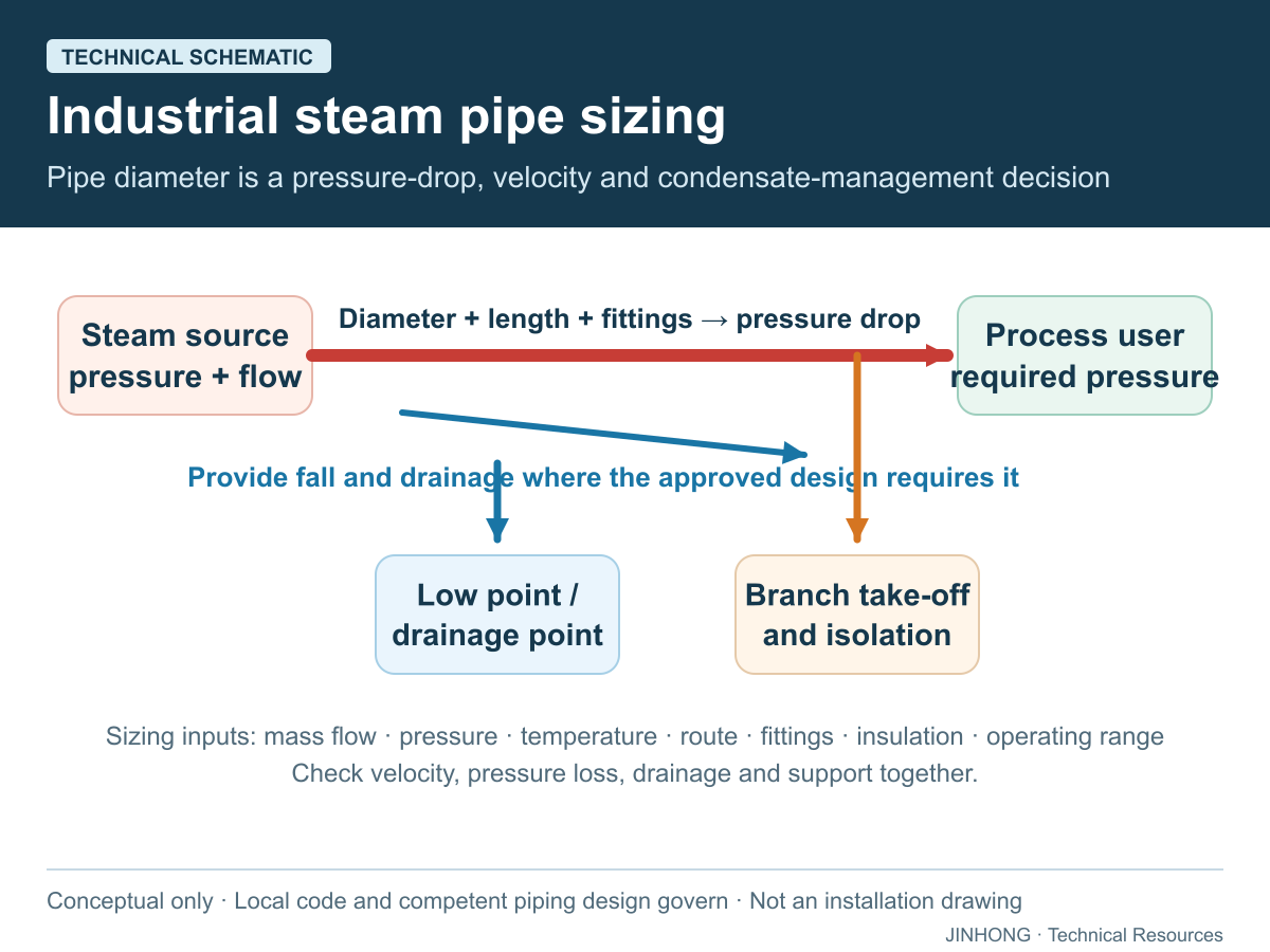
An industrial steam pipe should be selected only after checking both velocity and pressure drop at the required mass flow. The result must then be reviewed for condensate drainage, expansion, supports, insulation, materials and the governing piping code. A diameter chosen from boiler capacity alone can still deliver inadequate pressure, wet steam or unstable operation at the process.
This guide supports preliminary project definition. Final pipe wall thickness, stress analysis, supports, welding, testing and legal compliance belong to the responsible piping engineer under the rules applicable at the installation site.
Collect the design basis before choosing a diameter
Begin with the maximum simultaneous steam flow for each main and branch, not simply the boiler nameplate. Record upstream pressure, minimum acceptable pressure at the user, saturated or superheated condition, total routed length, fittings, valves, elevation changes and insulation condition. Include startup demand where a cold network must be heated.
Pressure at the process can be materially lower than boiler pressure. The pressure-versus-working-pressure guide separates boiler design pressure, operating pressure, distribution losses and equipment demand. If a pressure-reducing valve is used, size the upstream and downstream sections for their different steam densities and verify the control valve separately.
Check velocity and pressure drop together
Velocity is calculated from volumetric flow divided by internal flow area. For steam, volumetric flow equals mass flow multiplied by specific volume at the relevant pressure and temperature. Because specific volume changes strongly with pressure, one pipe size cannot be selected from mass flow without knowing the steam condition.
Pressure-drop assessment must include straight pipe and the equivalent resistance of fittings, valves and other components. Spirax Sarco’s pipe-sizing guidance describes velocity and pressure-drop methods and notes the tradeoff between an oversized, costly main and an undersized main with excessive loss, noise and erosion risk. Its example velocities are guidance for stated conditions, not universal JINHONG design limits.
An illustrative velocity check
Assume, only for arithmetic, a saturated-steam flow of 1,000 kg/h and an assumed specific volume of 0.24 m³/kg. The volumetric flow is 240 m³/h, or 0.0667 m³/s. If the proposed pipe has an actual internal diameter of 80 mm, its area is π × 0.08² ÷ 4 = 0.00503 m², giving an average velocity of about 13.3 m/s.
This is not a pipe recommendation. The assumed specific volume must be replaced with a verified steam-table value, the real internal diameter must come from the selected pipe schedule, and pressure drop must still be calculated across the routed system.
Protect the pressure required at every user
Build the distribution model from the boiler header to the most demanding user. Allocate the available pressure loss across the main, branches, separators, meters, control valves and final equipment. A line that works at average demand may fail when multiple users open together. Conversely, maintaining unnecessarily high boiler pressure to hide a restrictive pipe can raise losses and does not correct poor distribution design.
Where loads fluctuate, review the main under maximum simultaneous demand and credible minimum flow. High velocity at peak load and poor control at low load may both matter. If demand changes rapidly, also review the boiler turndown and sequencing rather than treating pipe diameter as the only cause of pressure instability.
Design condensate drainage with the steam main
Heat loss forms condensate during startup and normal operation even when piping is insulated. Spirax Sarco’s steam-main guidance explains that accumulated condensate can contribute to corrosion, erosion, wet steam and waterhammer. The route therefore needs deliberate slope, drain pockets at appropriate locations, correctly selected steam traps and dry branch takeoffs. Exact spacing and geometry must follow the project conditions and responsible engineer’s design.
Drainage is not repaired by increasing the steam pressure. Review low points, vertical rises, closed-valve pockets and outdoor sections. Link the pipe plan to the steam-trap selection guide and waterhammer prevention guide. Returned condensate must also enter a properly engineered recovery route; see condensate recovery design.
Complete the mechanical and code review
ASME B31.1 describes minimum requirements for design, materials, fabrication, erection, examination, testing, operation and maintenance within its scope. Other projects may fall under different national or process-piping rules. The owner and piping engineer must identify the governing code and jurisdiction rather than selecting one from an online article.
Complete the review with pipe schedule and material, design pressure and temperature, corrosion allowance where applicable, flexibility and thermal expansion, support loads, drainage, vents, valve access, insulation and personnel protection. DOE guidance identifies uninsulated steam and condensate lines as continuing heat-loss sources, but actual insulation thickness and economics require the real environment and operating hours.
Coordinate the distribution system with the complete boiler package. Boiler outlet size is an interface, not proof that the entire plant main should use that diameter.
Frequently asked questions
Can steam pipe size be selected from metric tons per hour alone?
No. Pressure, steam condition, allowable loss, routed length, fittings and actual internal diameter are also required.
Should velocity or pressure drop control the selection?
Both must be checked. The controlling criterion can change with pipe length, pressure, layout and the process requirement.
Why can pressure fall when the boiler appears adequate?
Possible causes include excessive pipe resistance, simultaneous demand, restrictive valves, poor control, wet steam or an incorrect pressure basis. Measurements are needed before assigning the cause.
Does a larger pipe always improve the system?
No. Oversizing increases cost, surface area, warm-up demand and condensate formation. The selected size should satisfy the complete hydraulic and mechanical design.
Send JINHONG the steam flow, pressure, layout and user schedule so the boiler-system interfaces can be reviewed before the site piping is finalized.
Technical references
Primary and official sources consulted for this guide. Source publication dates, jurisdictions and equipment contexts differ; examples are not JINHONG performance claims.