
Steam Condensate Recovery: Design Checks Before Returning Water to the Boiler
A practical design review for recovering useful condensate heat and water without compromising boiler water quality or equipment drainage.
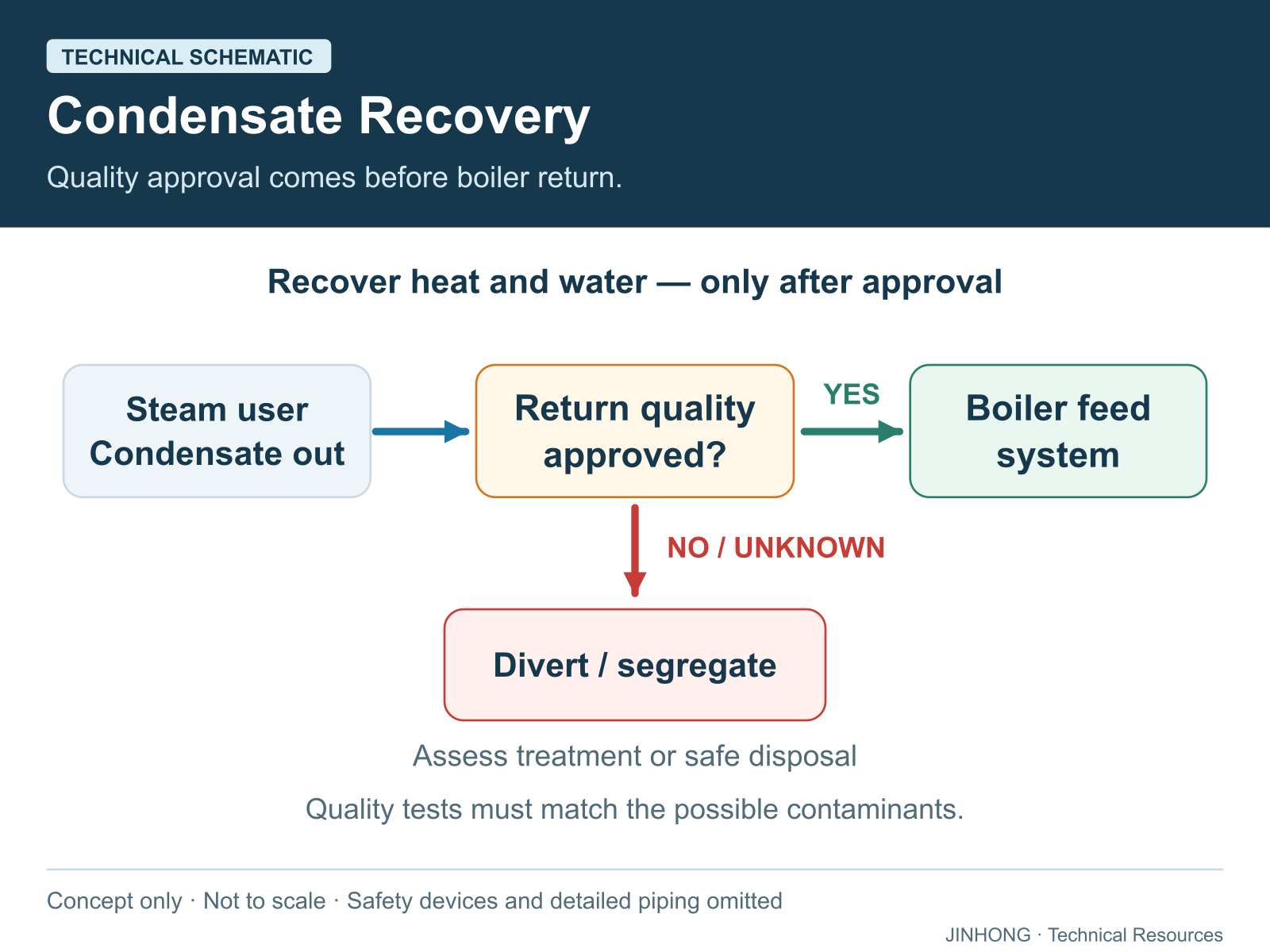
Open full-size technical schematic ↗
Steam condensate recovery connects production equipment back to the boiler house. A useful project does more than collect hot water: it identifies which water is suitable for return, checks whether every steam user can drain, and finds a reliable destination for the recovered energy. This guide explains the decisions to document before selecting a return tank, pump or flash vessel.
What value remains in condensate?
After steam transfers heat and becomes liquid, that liquid still contains sensible heat. Returning suitable condensate can reduce cold make-up water demand and the energy needed to heat the boiler feedwater. It can also reduce the amount of new water requiring treatment. These are separate benefits, not a guaranteed percentage saving for every factory. Spirax Sarco explains the underlying heat and water benefits in its introduction to condensate recovery.
Draw the recovery boundary first
Prepare a simple source register before discussing equipment prices. For each steam user, record the following:
- Equipment identification and whether steam contacts the product directly or heats through a separating surface.
- Condensate flow during normal production, start-up and batch transitions.
- Available pressure at the equipment outlet, including low-load conditions.
- Return destination, route length, elevation changes and other connected users.
- Possible process contaminants and the evidence needed to approve return.
A useful deliverable is a marked-up process drawing with each connection classified as approved, conditional or excluded. Unknown sources should remain conditional until assessed. This prevents an attractive combined flow total from concealing one unsuitable branch.
Protect the boiler against contamination
Condensate originating as steam is not automatically safe after travelling through equipment. A leaking heat-transfer surface can introduce process material. Unsuitable return water can contribute to boiler foaming, deposits or corrosion. Conductivity monitoring can detect certain changes and support an engineered diversion arrangement, as described in Spirax Sarco’s contaminated-condensate guidance.
Define the credible contaminant with the process owner and water-treatment specialist; do not assume one sensor proves all aspects of water quality. Specify the sampling method, acceptance criteria, instrument response and action following an alarm. Where direct return cannot be approved, evaluate separately whether heat can be recovered through a suitable heat exchanger. Boiler-feed approval and wastewater-discharge approval are different decisions. See also boiler feedwater and treatment basics.
Turn each source into an approval record
Use one record per condensate source. The table identifies evidence to obtain; it does not approve a source or prescribe universal water-quality limits.
| Input | Record required | Review owner |
|---|---|---|
| Source identity | Equipment tag, process contact and potential contamination route. | Process owner |
| Quality evidence | Sample location, operating condition, laboratory result and applicable acceptance criteria. | Water-treatment specialist |
| Return conditions | Flow, temperature, limiting outlet pressure, backpressure and destination. | System designer |
| Protection and decision | Detection suitability, diversion assessment, approval status, reviewer and date. | Responsible site engineer |
Link each result to the feedwater treatment plan and retain unresolved items as conditional. A satisfactory sample does not establish how quality changes during every production condition.
Check drainage at the weakest pressure condition
A return system must not prevent the production equipment from draining. Return-line pressure, vertical lift and friction oppose condensate discharge. With temperature-controlled equipment, the steam-side pressure may fall as demand decreases; a drainage arrangement that works at full output may therefore be unsuitable at light load. The same Spirax Sarco guidance explains why lifting condensate from low-pressure, controlled equipment may require an engineered pump-trap arrangement.
Record the limiting operating condition rather than using boiler nameplate pressure for every calculation. The distinction between generation pressure and process pressure is covered in boiler pressure versus equipment working pressure.
Allow for flash steam, not just liquid flow
When sufficiently hot condensate enters a lower-pressure system, some liquid evaporates. This is flash steam, not evidence by itself that a trap is leaking. Its quantity depends on the entering condensate enthalpy and the downstream pressure. A flash vessel can separate the vapour for an appropriate lower-pressure heat user. Recovery is useful only when a compatible demand exists; seasonal or intermittent demand needs particular scrutiny. See Spirax Sarco’s flash-steam recovery tutorial.
The vapour occupies much more space than the liquid. Trap discharge collectors carrying flashing condensate therefore require two-phase assessment, rather than water-only pipe sizing. Pipe route, pressure drop and simultaneous discharges matter alongside total mass flow. TLV explains this distinction in condensate recovery piping.
Build a savings estimate that can be checked
Use measured or explicitly assumed flows, temperatures and annual operating hours. As a preliminary liquid-heat calculation, recovered heat is approximately mass flow multiplied by water’s specific heat capacity and the temperature difference relative to replacement water. This is a screening calculation, not a complete steam-system simulation. Flash-vapour recovery requires an enthalpy balance, and heat lost before the boiler house must not be counted as recovered.
Usable recovered heat is not the same as avoided fuel input. For screening, divide that heat by the appropriate baseline or incremental boiler efficiency, using a consistent HHV or LHV basis. Spirax Sarco includes boiler efficiency in its condensate fuel-savings calculation.
Separate the business case into avoided fuel, water and treatment costs, then subtract pumping, maintenance and other operating costs. Avoid counting the same energy once as hot-water recovery and again as flash-steam recovery. Show a low, expected and high operating-hours case instead of presenting a single optimistic payback. After installation, compare the same production conditions and retain the original assumptions beside the measured result.
A hypothetical liquid-heat calculation with a defined boundary
Assume approved liquid condensate arrives at the boiler house at 600 kg/h and 80°C, replacing make-up water at 20°C for 4,000 h/year. These are invented calculation inputs, not operating targets or JINHONG project results. Use an approximate water heat capacity of 4.18 kJ/(kg·K).
| Quantity | Calculation and units |
|---|---|
| Temperature difference | 80 − 20 = 60 K |
| Liquid heat rate | 600 kg/h × 4.18 kJ/(kg·K) × 60 K = 150,480 kJ/h = 41.8 kW |
| Annual liquid heat | 41.8 kW × 4,000 h/year = 167,200 kWh/year |
| Fuel-energy equivalent | Assume 80% applicable boiler efficiency on an LHV basis: 167,200 ÷ 0.80 = 209,000 kWh of fuel/year |
| Gross fuel-cost equivalent | Assume US$0.05/kWh of fuel on the same LHV basis: 209,000 × 0.05 = US$10,450/year |
The boundary uses arriving liquid, so upstream flash steam and heat lost along the return route receive no separate credit. Pump electricity, maintenance, capital cost, water charges, treatment changes and blowdown effects are excluded. This is a gross screening estimate, not net savings or payback.
Verify arrival flow and temperature together, actual annual availability, marginal fuel response and the tariff before using the result in a business case. Keep the boiler-efficiency measurement boundary consistent. Site fuel savings require comparison under equivalent production conditions; the assumed efficiency does not guarantee them.
Frequently asked questions
Should every condensate line return to the boiler?
No. Approve each source for water quality and hydraulic compatibility. A high return percentage is not a useful target if the returned water is unsuitable.
Does a visible plume prove that a steam trap failed?
No. Flashing can occur during normal condensate discharge. A qualified survey must distinguish expected flash steam from live-steam leakage.
What should be supplied for a recovery review?
Provide the source register, operating pressures, flow estimates, water analyses and a route drawing. Identify which values are measured and which remain assumptions.
For a boiler-system enquiry, include these records with your technical proposal request. This article is design guidance, not a substitute for site-specific pressure-system engineering or operating procedures.
Technical references
Primary sources consulted for this guide. Source publication dates and equipment contexts differ; historical examples are not JINHONG performance claims.