
Industrial Boiler Room Layout: Clearances, Ventilation, Drainage and Maintenance Access
A pre-purchase boiler-room planning guide covering the equipment envelope, access, lifting, combustion and cooling air, drainage, foundations, flue routing and responsibility boundaries.
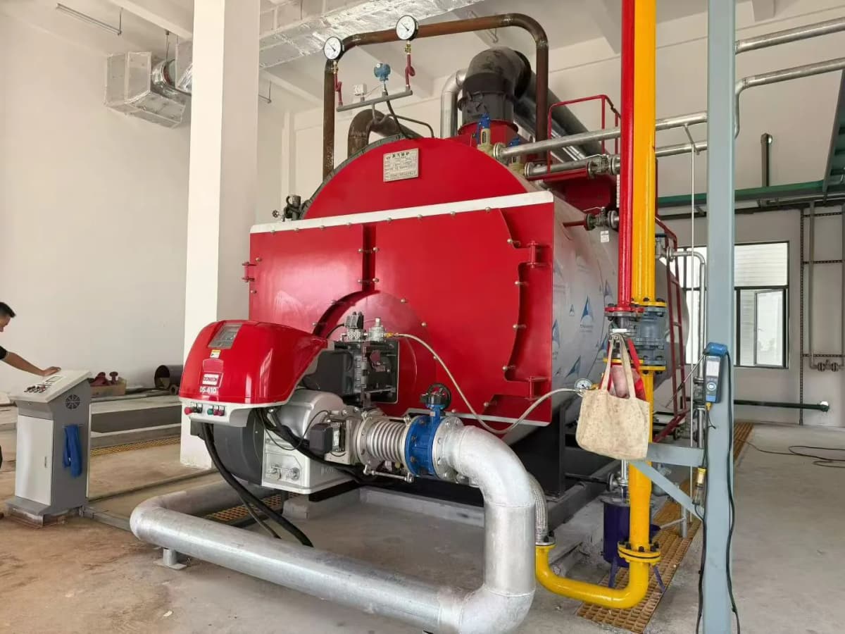
A reliable industrial boiler room layout begins with the operating and maintenance envelope of the complete plant, not a rectangle drawn around the boiler body. The room must accommodate delivery, installation, burner or grate service, pressure-part inspection, water treatment, pumps, controls, fuel equipment, flue-gas components, drainage and safe access.
There is no universal clearance or ventilation opening that can be copied into every project. Equipment drawings, fuel input, local building and fire rules, applicable boiler standards, climate and the authority having jurisdiction all affect the final arrangement. This guide organizes the questions that should be resolved before JINHONG equipment is released for manufacture.
Freeze the equipment and service envelope first
Start with certified general-arrangement drawings for the offered boiler and auxiliaries. Record the operating weight when filled, lifting points, center of gravity where required, door-swing areas, burner withdrawal distance, tube-cleaning or coil-access direction, ash-removal route and the access needed for valves, gauges and safety devices.
Bosch’s installation planning guidance emphasizes access to mounted valves, sensors and inspection openings, together with foundation capacity and equipment transport openings. Its example clearances are tied to its systems and local context; they are not JINHONG values. Final dimensions must come from the approved project drawings.
Allow a continuous route for operators and emergency response. Do not use required service space for spare-part storage, fuel bags or temporary production equipment. Review the complete boiler-system components before concluding that the room is large enough.
Plan delivery, assembly and future replacement
Verify the route from the unloading point to the final foundation: gate width, turning radius, floor loading, overhead obstructions, crane access, roof openings and the dimensions of every component. A boiler that fits its final position may still be impossible to move through the building.
Sectional or field assembly creates additional working space, temporary lifting and quality-control needs. Leave a practical route for future removal of the burner, motor, pump, heat exchanger, economizer elements or other heavy parts. The JINHONG manufacturing and quality page shows why equipment identification and inspection records should remain connected from fabrication through installation.
Engineer combustion air and room ventilation
Fired equipment needs combustion air, while the room may also need air movement to remove heat and maintain suitable conditions for controls and personnel. Exhaust fans elsewhere in the building can change room pressure and affect the flue system. Air openings must therefore be sized from the complete installed fuel input and local rules, not from boiler floor area alone.
NFPA 54 includes sections on appliance installation, venting and indoor/outdoor combustion-air calculations for gas-fired systems. Applicability depends on the jurisdiction and equipment. Bosch likewise states that supply and extract air must be planned around the combustion system and other air consumers. The responsible engineer must also prevent corrosive, dusty or contaminated process air from entering the burner.
Solid-fuel plants add dust, fuel handling and ash routes. Separate these activities where required and prevent them from blocking access or contaminating control equipment. Never reduce an air opening or add a room exhaust fan without reviewing combustion and flue behavior.
Coordinate foundation, drainage and utilities
The civil designer needs maximum operating weights and load locations for the boiler, feedtank, deaerator, pumps, chimney supports and water-treatment equipment. Foundations should support the installed plant and preserve alignment. Vibration and noise measures must be selected for the actual burner, fans, pumps and building structure.
Plan drainage for water-treatment discharge, controlled blowdown cooling, equipment drains and maintenance washdown. Hot water, steam or treatment chemicals must not be discharged to an unsuitable open floor drain. Define safe collection, cooling, neutralization or disposal according to the project and local environmental requirements.
Map fuel, water, steam or hot-water, condensate, power, compressed air, controls and communications. Protect electrical panels from heat, water and vibration while keeping them accessible. The JINHONG service workflow can be used to define which interfaces require installation guidance and commissioning records.
Lay out the flue route and maintenance access together
The flue-gas path includes the boiler outlet, economizer or condenser where used, dust-control equipment for solid fuel, induced-draft fan, ducts and chimney. Check support loads, thermal expansion, drain points, inspection doors, cleaning access, corrosion conditions and the effect of pressure loss on the selected fan.
Keep discharge locations and air intakes from interfering with each other under the applicable rules and site wind conditions. A short duct is not automatically acceptable if it prevents access or creates an unsafe discharge arrangement. Real projects such as the 6 TPH SZL system in Uzbekistan show why boiler and flue-gas equipment need one coordinated site plan. The Vietnam two-boiler heating project illustrates a different arrangement; neither photograph is a template for another site.
Use a written interface and responsibility matrix
| Interface | Information to freeze | Responsible party to name |
|---|---|---|
| Equipment | Models, dimensions, operating weights and service envelopes | Equipment supplier and project engineer |
| Civil work | Foundation, openings, drainage and structural supports | Local civil designer and contractor |
| Fuel and flue | Supply conditions, air, duct route, fan and stack | Combustion/flue specialists |
| Utilities | Water, power, steam, condensate and controls | Site engineering team |
| Approval | Permits, inspection, tests and records | Owner and local authorized parties |
HSE guidance stresses competent management, equipment documentation and review of operational changes. Its UK legal framework is not automatically applicable elsewhere, but the management principle is useful: approved limits and responsibilities must be recorded and kept available.
Frequently asked questions
How much clearance does an industrial boiler need?
There is no single answer. Use the exact equipment drawings, service tasks, lifting method, applicable code and local authority requirements.
Can the boiler be installed outdoors?
Some project configurations can be engineered for outdoor installation, but weather, freezing, corrosion, controls, access, noise and local approval must be addressed explicitly.
Can room ventilation be sized from boiler capacity alone?
No. Fuel input, burner air, other room exhausts, heat release, pressure interaction and governing rules must be evaluated together.
Who designs the foundation and chimney?
The supply boundary must state this. Equipment loads and interface data come from the approved supplier documents; local structural and chimney design normally requires qualified destination-site professionals.
Send JINHONG the site plan, openings, utilities, fuel and local requirements so installation interfaces can be identified before the final proposal.
Technical references
Primary and official sources consulted for this guide. Source publication dates, jurisdictions and equipment contexts differ; examples are not JINHONG performance claims.