
Thermal Oil Heater System Design: Expansion Tank, Circulation and Film Temperature
A thermal oil heater is one part of a closed circulation loop. Fluid selection, expansion capacity, pump duty, coil velocity, film temperature and process control must be engineered together.
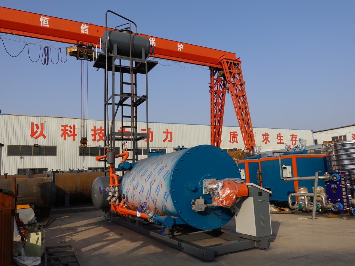
A dependable thermal oil heater system is designed as a complete circulation loop, not selected from heater power alone. The process duty sets the heat requirement, but the fluid properties, operating temperatures, expansion volume, pump conditions, heater-coil velocity, user pressure drop and control philosophy determine whether that heat can be transferred safely and consistently.
JINHONG offers gas/oil, biomass and electric thermal-oil routes. The correct route begins with the process heat balance and the approved heat-transfer fluid, not a copied flow rate or expansion-tank percentage.
Define the process and fluid operating envelope first
Record the required process inlet and outlet temperatures, heat-up time, steady duty, batch or continuous pattern, number of users, minimum ambient temperature and shutdown conditions. Then obtain the selected fluid supplier’s density, viscosity, vapor pressure and permitted bulk and film-temperature limits over that range.
Eastman’s fluid-selection material shows that different heat-transfer fluids have different liquid-phase and temperature envelopes. Source: Eastman Therminol — heat-transfer-fluid selection. Product data from one fluid must not be applied to another, and the fluid supplier’s current technical data and safety information remain controlling inputs.
Keep bulk temperature and film temperature separate
Bulk temperature is the mixed fluid temperature measured in the circuit. Film temperature is the local temperature close to the heated tube wall. The film can be hotter than the bulk fluid because heat must cross that boundary layer. Low circulation, an obstructed path, excessive heat flux or deposits can increase the difference and accelerate fluid degradation even when the outlet display appears acceptable.
A thermal oil heater system design should therefore define minimum circulation through the heater, coil pressure drop, bypass conditions, start-up viscosity and the response to loss of flow. Eastman’s system-design guidance emphasizes the balance among heating capacity, fluid velocity, bulk temperature and film temperature. Source: Eastman Therminol — heat-transfer system design resources.
Size the circulation route from the complete pressure-drop curve
The pump must cover the heater coil, process users, piping, fittings, valves and any control or filtration devices at the required flow. Density and viscosity change with temperature, so cold start and normal operation can present different conditions. NPSH margin, suction arrangement, seal compatibility and standby philosophy need project-specific review.
Do not throttle the design into compliance after installation. Build a system curve, identify the controlling user and confirm how parallel branches will be balanced. The YY(Q)W gas/oil heater, YLW biomass heater and YDW electric heater use different heat sources, but each still depends on a verified oil circuit.
Calculate expansion from fluid density—not a generic tank ratio
For an illustrative mass-conservation check, assume a system contains 10,000 L of fluid at the cold fill condition. If its assumed density changes from 900 kg/m³ cold to 760 kg/m³ hot, the calculated hot volume is 10,000 × 900 ÷ 760 = 11,842 L. The thermal expansion is therefore about 1,842 L.
This result is not the required vessel size. The final expansion-tank design must also accommodate minimum and maximum operating levels, vapor space, venting or inert-gas arrangement, alarms, relief routing, reserve volume and local requirements. Eastman’s expansion-tank resource explains why the vessel and its connection belong inside total system design. Source: Eastman Therminol — heat-transfer system expansion-tank design.
Protect the fluid during operation, shutdown and maintenance
Oxidation, moisture, contamination and overheating can change fluid condition. A design review should define sampling points, strainers or filtration where applicable, drain and fill arrangements, leak management and the evidence required before returning a circuit to service. Fluid analysis must be interpreted against the fluid supplier’s criteria; color alone is not a complete condition test.
Controls commonly coordinate heater firing or electric stages with pump operation, flow proof, outlet and return temperature, expansion-tank level and emergency shutdown. Exact set points and cause-and-effect logic belong to the approved design. Do not bypass circulation interlocks to maintain production after a pump or flow alarm.
Match the JINHONG heater to a documented system boundary
The proposal should identify the heater, pumps, expansion tank, oil reservoir, controls, valves, instrumentation, process heat exchangers, piping and local work. Start by comparing steam, hot water and thermal oil, then use the complete-system boundary to assign interfaces. Send heat duty, temperature profile, fluid name, electrical or fuel data, piping layout and destination through the technical proposal form.
Frequently asked questions
Is thermal oil outlet temperature the same as film temperature?
No. Outlet temperature represents the bulk fluid, while film temperature is local to the heated surface and can be higher. Both limits must be checked with the heater and fluid suppliers.
Can an expansion tank be sized as one fixed percentage of system volume?
Not reliably. Expansion depends on the selected fluid’s density change and temperature range, while vessel capacity also depends on operating levels, venting, reserve and code requirements.
Does a larger circulation pump always protect the heater?
No. The pump must match the system curve, fluid properties and required flow without creating unsuitable pressure, control or NPSH conditions. Selection requires a hydraulic calculation.
Technical references
Primary and official sources consulted for this guide. Source publication dates, jurisdictions and equipment contexts differ; examples are not JINHONG performance claims.