
ELECTRIC THERMAL FLUID HEATING
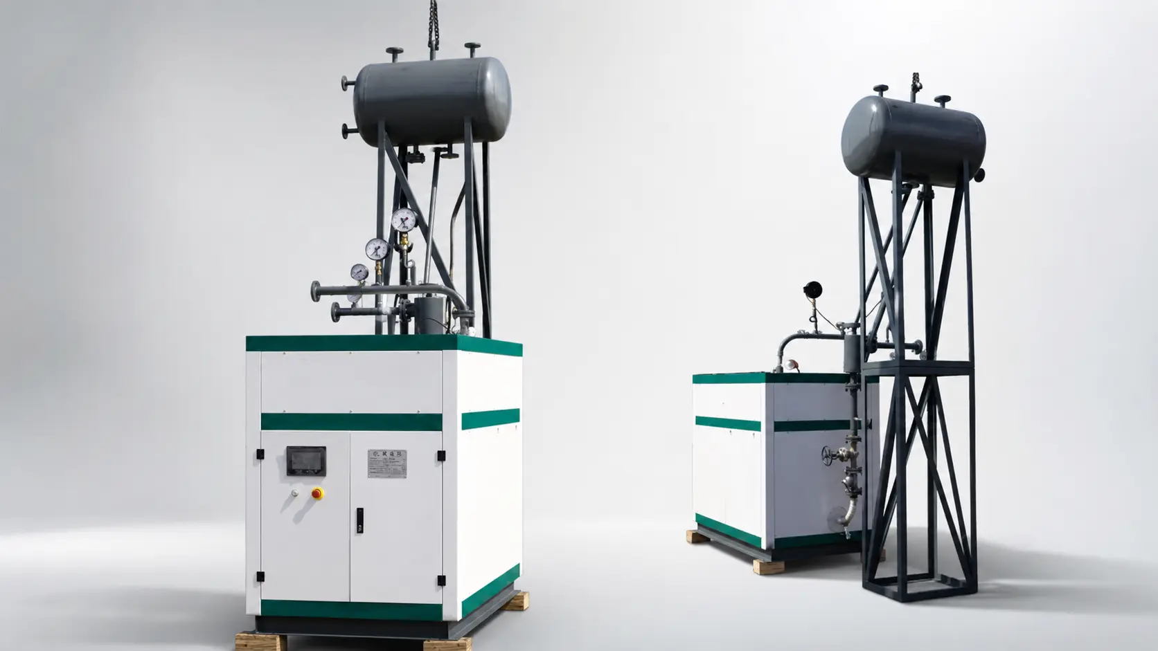
YDW Electric Thermal Oil Heater
High-temperature process heat without a burner, using electric elements and forced thermal-oil circulation for stable, controllable operation.
- Verified Duty
- 600 / 700 kW
- Working Pressure
- 0.7 MPa
- Oil Temperature
- 300 / 280°C
- Power Supply
- 380 V / 50 Hz
PRODUCT OVERVIEW
Electric Heat for Closed-Loop Thermal-Oil Systems.
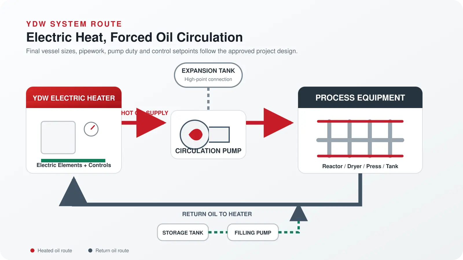
The YDW series uses electric heating elements to raise the temperature of circulating thermal oil. The oil transfers heat to reactors, dryers, presses, tanks or other process equipment before returning to the heater.
The two verified configurations on this page are 600 and 700 kW, both with 0.7 MPa working pressure and rated 300°C supply / 280°C return oil temperatures.
YDW Electric Heater
Electric elements provide process heat without a burner, fuel train, chimney or combustion-air system.
Forced Circulation
High-temperature oil pumps circulate heat through the user equipment and back to the heater.
Duty / Standby Pumps
The verified system uses two 15 kW circulation pumps, arranged as one operating and one standby.
Project Engineered
Electrical supply, transformer, cabling, oil volume, piping and control setpoints are confirmed for each site.
WORKING PRINCIPLE
Electric Elements Heat the Oil; the Pump Delivers Heat to the Process.
After the circulation pump establishes the required oil flow, the controller enables the electric heating stages. The heated oil flows to the process equipment, releases part of its heat and returns to the heater for reheating.
Temperature, pressure and flow conditions are monitored through the control and interlock system. Heater operation is coordinated with pump status so electric elements are not energized without the required circulation condition.
VERIFIED TECHNICAL DATA
YDW 600 and 700 kW Configurations.
The values below describe the two confirmed configurations. Final pump duty, connections, incoming feeder, cable arrangement and protection settings follow the approved electrical and general-arrangement drawings.
| Item | YDW-600KW-D | YDW-700KW-D |
|---|---|---|
| Rated Thermal Duty | 600 kW | 700 kW |
| Working Pressure | 0.7 MPa | 0.7 MPa |
| Rated Outlet Oil Temperature | 300°C | 300°C |
| Rated Return Oil Temperature | 280°C | 280°C |
| Heater Body Oil Volume | 0.3 m³ | 0.3 m³ |
| Electric Input Range | 60-600 kW | 70-700 kW |
| Rated Electric Input | 600 kW | 700 kW |
| Power Supply | 380 V / 50 Hz | 380 V / 50 Hz |
| Voltage / Frequency Tolerance | ±5% / ±1% | ±5% / ±1% |
| Recommended Transformer Capacity | 900 kVA | 1100 kVA |
| Controller | JHDK-600 | JHDK-700 |
| Hot-Oil Circulation Pumps | 15 kW × 2; one duty, one standby | 15 kW × 2; one duty, one standby |
| Filling Pump | 1.5 kW × 1 | 1.5 kW × 1 |
| Installation | Indoor | Indoor |
Electrical interface: The listed transformer capacity is a recommendation for these configurations. Confirm the available supply, short-circuit capacity, incoming feeder, harmonics requirements, earthing and local electrical rules.
Hydraulic interface: Final pipe size, pump head, flow rate, expansion volume and valve selection depend on the oil properties, system volume, elevation, pressure drop and process equipment.
SYSTEM ROUTE
Engineer the Heater and the Complete Oil Circuit Together.
Stable heating depends on the complete loop: heater, pumps, process equipment, expansion volume, piping, instruments, oil quality and control logic.
PROJECT ENGINEERING
Confirm the Heat Load and Electrical Infrastructure Before Selection.
A reliable proposal must match the real heating duty, oil circuit and site power system. Share both the normal operating condition and the required warm-up time.
Send project data →- 01Process Heat Load
Provide material throughput, operating temperature and heat demand.
- 02Heating Curve
Define starting temperature, target temperature and permitted warm-up time.
- 03Thermal Oil
Provide oil type, allowable film temperature and operating viscosity.
- 04System Volume
Confirm heater, piping and user-equipment oil volumes.
- 05Hydraulic Resistance
Provide piping length, elevation, fittings and equipment pressure drop.
- 06Electrical Supply
Confirm voltage, frequency, transformer, feeder capacity and site rules.
SUPPLY SCOPE
Define Every Included Item and Site Interface.
The technical proposal identifies the packaged equipment and the customer’s electrical, civil, piping, installation and process responsibilities.
Transformer, incoming feeder, complete plant piping, process equipment, thermal oil, civil works, installation and local approvals are included only when explicitly stated in the agreed supply scope.
APPLICATIONS
High-Temperature Process Heating Without On-Site Combustion.
Application suitability is confirmed from heat load, oil temperature, heating curve, area classification, electrical infrastructure and process safety requirements.
Chemical Reactors
Controlled jacket or coil heating for batch and continuous processes.
Rubber & Plastics
Thermal-oil supply for presses, molding, vulcanizing and production lines.
Drying & Coating
Process heat for dryers, ovens and coating equipment.
Textile Processing
Stable heat supply for dyeing, finishing and heat-setting equipment.
Food & Oils
Indirect process heating after hygiene and oil-system requirements are confirmed.
Tanks & Heat Exchangers
Heating duties for storage, transfer and process heat-exchange systems.
FREQUENTLY ASKED QUESTIONS
YDW Electric Thermal Oil Heater FAQ.
What YDW capacities are listed on this page?
This page lists the two verified configurations: YDW-600KW-D and YDW-700KW-D.
What are the rated oil temperatures?
Both listed configurations are rated at 300°C outlet oil temperature and 280°C return oil temperature.
Does the system need a circulation pump?
Yes. Thermal oil is moved by forced circulation. The listed configuration uses two 15 kW hot-oil pumps arranged as one duty and one standby.
How large should the transformer be?
The recommended transformer capacity is 900 kVA for the 600 kW configuration and 1100 kVA for the 700 kW configuration. The final electrical design must verify the complete site load and incoming supply.
Can the heater be selected from electrical power alone?
No. The process heat load, warm-up time, oil type, system volume, hydraulic resistance and electrical infrastructure must be checked together.
Is all site piping included?
Only items explicitly listed in the agreed proposal are included. Complete plant piping, installation, thermal oil, transformer and process equipment are normally treated as defined project interfaces.
TECHNICAL SELECTION
Send the Heat Load, Heating Curve and Available Electrical Supply.
Share the process duty, oil temperatures, system volume, warm-up time, voltage, frequency and transformer capacity for a matched YDW proposal.