
GAS / OIL FIRED THERMAL OIL HEATER
YY(Q)W Gas/Oil Thermal Oil Heater
Indirect high-temperature process heating engineered around actual heat duty, supply and return temperature, thermal-oil selection, fuel conditions and the customer’s process system.
- Rated Thermal Power
- 120–10,000 kW
- Design Pressure
- 1.0 MPa
- Outlet Temperature
- ≤350°C
- Available Fuels
- Gas / Oil
PRODUCT OVERVIEW
Controlled Heat Transfer for Processes That Need More Than Steam or Hot Water.
The YY(Q)W series is a gas- or oil-fired organic heat-carrier heater, commonly specified internationally as a thermal oil heater. Combustion heats a coil-type heating surface while a circulation pump moves thermal oil through the heater and the customer’s process heat exchangers.
This liquid-phase circulation route can deliver high process temperatures at comparatively lower system pressure than steam at similar temperatures. It is not a zero-pressure system: design pressure, expansion, flow, temperature, safety interlocks and applicable codes must all be engineered for the selected thermal oil and process.
Indirect Process Heating
Thermal oil transfers energy to process users without mixing combustion products or the heat carrier with the process material.
Closed Circulation Route
The configured pump, heater, process users and return line form a controlled loop with expansion and venting provisions.
Gas or Oil Firing
The burner and fuel train are selected for the available natural gas, city gas, light oil or approved heavy-oil conditions.
Project-Defined Package
Skid arrangement, pumps, tanks, controls, valves, chimney and process interfaces are defined from the actual plant boundary.
THERMAL-OIL CIRCUIT
One Engineered Route from Combustion to the Process and Back.
The burner releases heat into the heater’s radiant and convection sections. Thermal oil circulating inside the coil absorbs that heat, flows to the process heat exchanger and returns at a lower temperature for reheating.
Flow confirmation, differential pressure, outlet and return temperature, burner modulation, expansion level and protective shutdowns must work together. Stable circulation is required before and during firing so that the heat-transfer surface remains within the approved film-temperature limit.
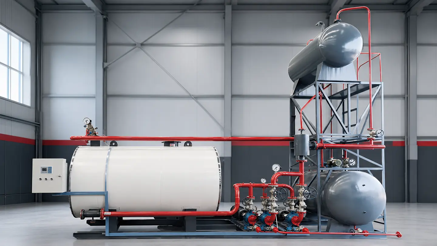
REFERENCE SYSTEM DIAGRAM
How the Heater Connects to the Complete Thermal-Oil Circuit.
This simplified diagram helps define the main equipment and flow direction. Final pipe sizes, elevations, valves, instruments, tank volumes and control points follow the approved project calculation and drawings.
DESIGN FEATURES
The Heater Body, Circulation System and Safety Logic Are Designed as One Package.
These features describe the JINHONG YY(Q)W product route. Final coil geometry, burner, instruments, pumps, tanks, materials and control logic follow the approved calculation, proposal and drawings.
01 / HEATING SURFACE
Coil-Type Heat Transfer
Concentric coil surfaces create the defined combustion and oil-flow route within the heater body.02 / CIRCULATION
Liquid-Phase Oil Loop
Matched pumps maintain the calculated flow needed to carry heat safely from the heater to the process.03 / COMBUSTION
Matched Gas or Oil Burner
Burner turndown, fuel pressure, gas-train or oil-train components and controls are selected by project.04 / INSTALLATION
Skid-Mounted Arrangement
Heater, pumps, tanks and controls can be coordinated on a compact base where transport and site conditions permit.05 / EXPANSION
Expansion & Vent Boundary
System volume change, filling, deaeration, venting and oil storage are addressed in the complete circuit design.06 / PROTECTION
Integrated Interlocks
Flow, temperature, pressure, level, burner flame and pump status are coordinated in the approved protection logic.TECHNICAL DATA
Representative YY(Q)W Models from the JINHONG YY(Q)W product range.
The YY(Q)W product range supports initial selection from 120 to 10,000 kW. The representative models below are reference points—not substitutes for heat-load, hydraulic, thermal-oil and combustion calculations.
| Model | YY(Q)W-700Y(Q) | YY(Q)W-1400Y(Q) | YY(Q)W-2400Y(Q) | YY(Q)W-3500Y(Q) | YY(Q)W-4700Y(Q) | YY(Q)W-7000Y(Q) | YY(Q)W-10000Y(Q) |
|---|---|---|---|---|---|---|---|
| Rated Thermal Power kW | 700 | 1,400 | 2,400 | 3,500 | 4,700 | 7,000 | 10,000 |
| Heating Surface m² | 40 | 78.5 | 106.2 | 205.2 | 254.3 | 410 | 520 |
| Reference Light-Oil Use kg/h | 69 | 140 | 244 | 350 | 470 | 680 | 970 |
| Reference Natural-Gas Use Nm³/h | 83 | 170 | 296 | 425 | 570 | 810 | 1,160 |
| Oil Capacity in Heater m³ | 0.5 | 1.1 | 1.9 | 3.8 | 4.2 | 7.0 | 10.5 |
| Reference Overall Size mm | 3240 × 1470 × 2260 | 4145 × 1900 × 2786 | 5080 × 2200 × 3180 | 6555 × 2470 × 3634 | 7285 × 2570 × 3760 | 8200 × 3050 × 3800 | 10000 × 3500 × 4000 |
| Reference Transport Weight t | 3.7 | 6.7 | 9.8 | 17.8 | 21.5 | 27.5 | 32 |
Fuel consumption: technical data reference only. Actual consumption varies with fuel calorific value and properties, operating load, thermal-oil temperatures, excess air, ambient conditions and system losses.
Fuel range: Natural gas, city gas and light oil are common options. Heavy-oil use is available only where the selected model, burner, fuel preparation and local conditions are suitable.
Temperature: The listed ≤350°C is the heat-medium outlet limit in the YY(Q)W product range route. The permitted operating temperature must also comply with the selected thermal-oil supplier’s data and project design.
Dimensions and weight: Reference only. Use the approved general-arrangement drawing for transport, lifting, foundation, maintenance access and boiler-room planning.
PROCESS ENGINEERING
Size the Heater from the Process Heat Balance and Oil Circuit.
A reliable proposal separates normal heat duty from startup and peak demand. It then verifies temperature lift, circulation flow, pressure drop, thermal-oil condition, system volume, pump margin and the customer’s actual process interfaces.
Send process and fuel data- 01Useful Heat Duty
Provide normal, peak and startup loads for each user instead of selecting only from installed equipment rating.
- 02Supply & Return Temperature
The actual temperature difference affects oil flow, heat-transfer area, pump selection and control strategy.
- 03Thermal-Oil Selection
Confirm oil type, permitted bulk and film temperature, viscosity curve, oxidation condition and replacement plan.
- 04Hydraulic Resistance
Define pipe lengths, elevations, valves, heat exchangers and pressure drop before finalizing circulation pumps.
- 05Expansion & System Volume
Calculate fill volume, operating expansion, tank level, venting and oil-storage capacity for the whole circuit.
- 06Fuel & Site Conditions
Provide gas pressure and composition or oil specification, plus voltage, altitude, ambient conditions and destination codes.
HEATER & SYSTEM BOUNDARY
A Complete Thermal-Oil System Extends Beyond the Heater Body.
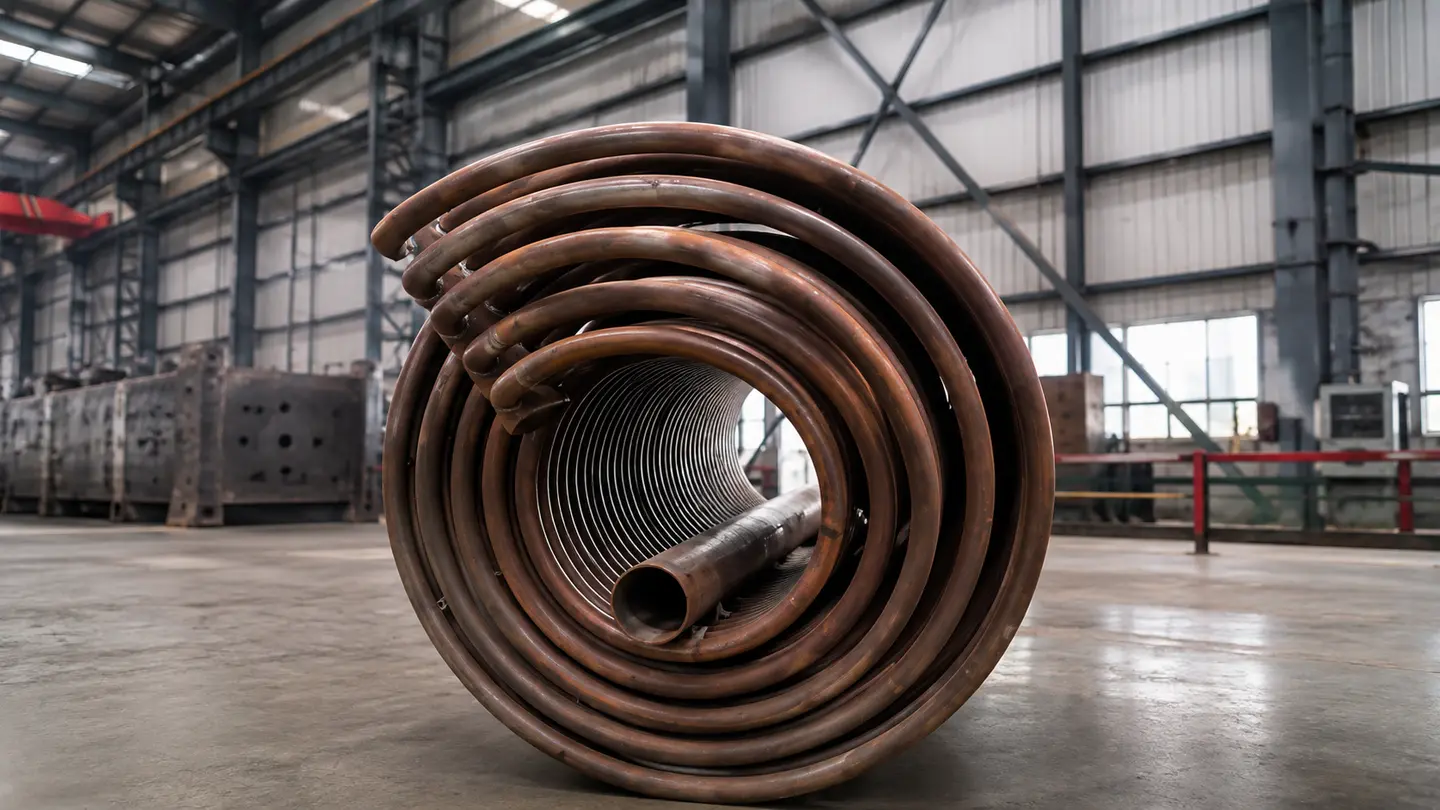
The heater must be coordinated with circulation, expansion, oil storage, venting, combustion, electrical control and every process user. The final supply boundary is listed line by line in the approved technical proposal.
Process heat exchangers, plant piping, thermal oil, civil works, installation, local approvals and customer utilities are included only when explicitly listed in the agreed supply scope.
Define the system boundaryAPPLICATIONS
Indirect High-Temperature Heat for Continuous Industrial Processes.
Application suitability depends on useful heat duty, temperature profile, process heat exchanger, thermal-oil compatibility, fuel and local safety requirements—not industry name alone.
Chemical & Reactor Heating
Jacketed reactors, distillation and process vessels that require stable indirect heating at controlled temperature.
Textile, Dyeing & Finishing
Dryers, stenters, calenders and other finishing equipment designed for a thermal-oil circuit.
Plywood & Wood Processing
Hot presses, veneer dryers and wood-product lines requiring uniform, repeatable indirect heat.
Rubber & Polymer Processing
Vulcanizing, mixing and forming processes subject to the actual heat-transfer and temperature requirements.
Food & Edible-Oil Processing
Fryers, deodorization, drying and jacketed process equipment with an approved indirect-heating boundary.
Asphalt & Bitumen Heating
Tanks, pipelines and process equipment where controlled high-temperature circulation is required.
FUEL & SELECTION GUIDANCE
Choose the Fuel Route Around Availability, Control and Operating Conditions.
Both gas and oil can serve the YY(Q)W heater when the burner, fuel train and plant infrastructure are correctly matched. A lifecycle comparison should include fuel quality, storage, utility reliability, emissions rules, maintenance and the actual operating profile.
Review industry solutions- 01Natural Gas
Often supports clean fuel handling and modulating control where stable gas pressure, flow and composition are available.
- 02Light Oil
Useful where liquid-fuel logistics are established; storage, transfer, filtration and fire-safety provisions must be defined.
- 03Heavy Oil Review
Requires confirmation of viscosity, heating, atomization, filtration, burner suitability and local emissions requirements.
- 04Dual-Fuel Option
Can be evaluated where fuel continuity is important, subject to burner range, fuel trains, controls and site approval.
- 05Operating Temperature
Never select only by a headline maximum; verify the process setpoint against thermal-oil bulk and film-temperature limits.
- 06Safety & Maintenance
Plan oil sampling, leak inspection, pump maintenance, interlock testing, emergency shutdown and controlled draining.
FREQUENTLY ASKED QUESTIONS
YY(Q)W Thermal Oil Heater FAQ.
What is the maximum thermal-oil outlet temperature?
The JINHONG YY(Q)W product range lists a heat-medium outlet temperature of up to 350°C. The permitted project setpoint may be lower and must comply with the selected oil’s bulk- and film-temperature limits, system design and local requirements.
Does a 1.0 MPa design pressure mean the system always operates at 1.0 MPa?
No. Design pressure is not the same as normal operating pressure. Actual pressure depends on circulation flow, system resistance, elevation, temperature, expansion arrangement and the approved project design.
Should I choose gas or oil firing?
Compare fuel availability, gas pressure or oil specification, price, storage, emissions rules, maintenance and reliability. JINHONG then matches the burner and fuel train to the selected route.
Can the complete thermal-oil system be skid-mounted?
A compact skid can be engineered for suitable capacities and transport conditions. Large systems or site constraints may require separate modules, tanks or field-installed piping.
How is the required heater capacity calculated?
Provide normal and peak useful heat duty, startup time, process mass and heat capacity, heat losses, supply and return temperatures, operating hours and simultaneous-load conditions. Selection is based on the heat balance rather than equipment name alone.
How do I select the thermal oil?
Review the required temperature, oil supplier’s bulk- and film-temperature limits, viscosity curve, oxidation stability, compatibility, service life and local safety requirements. The oil manufacturer and system designer should confirm the final grade.
What information is needed for a technical proposal?
Send process heat duty, supply and return temperatures, heat-up time, operating hours, thermal-oil details, gas pressure and composition or oil specification, site voltage and frequency, altitude, destination and preferred supply boundary.
START WITH PROCESS DATA
Get a YY(Q)W Proposal Matched to Your Heat Duty and Oil Circuit.
Send the normal and peak heat load, supply and return temperatures, heat-up time, process users, operating hours, thermal oil, fuel conditions and destination. JINHONG will define the heater, circulation route and supply boundary for technical review.