
Boiler Feed Pump Sizing: Flow, Head, NPSH and Cavitation Checks
A preliminary selection method for boiler feedwater pumps that connects steam output and blowdown to flow, then checks discharge head, control behavior, NPSH and the actual pump curve.
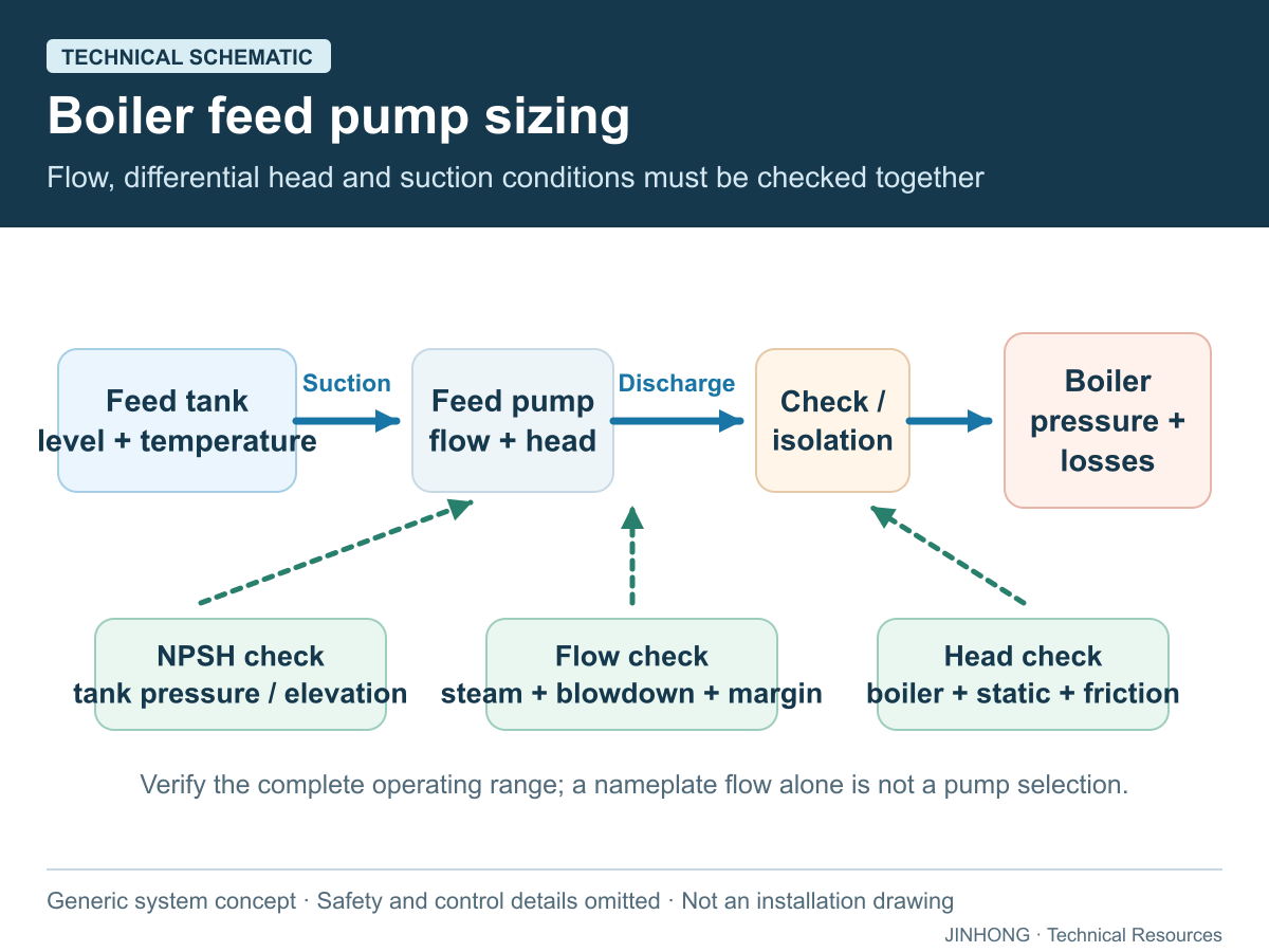
A boiler feed pump must deliver the required water flow at a discharge pressure above the boiler-side resistance while maintaining adequate suction conditions. Selecting it from steam capacity alone is incomplete. Feedwater temperature, tank elevation, line losses, control-valve differential, minimum-flow requirements and the manufacturer’s pump curve can change whether the proposed pump operates reliably.
This article provides a preliminary engineering sequence, not a final pump selection. The responsible boiler and pump engineers must verify the actual system, materials, motor, redundancy and applicable requirements.
Calculate the required feedwater flow
Begin with maximum continuous steam generation under the stated operating condition. Add continuous blowdown and any other water leaving the defined boiler boundary. Treat intermittent bottom blowdown separately so that a short event is not incorrectly added as a permanent flow unless the system design requires that basis.
Return condensate reduces cold makeup demand but does not normally eliminate the boiler’s need for feedwater equal to water leaving as steam and blowdown. Tank storage, makeup treatment and condensate return must therefore be evaluated separately. Review condensate recovery design and blowdown control before fixing the material balance.
An illustrative flow calculation
Assume a boiler produces 2,000 kg/h of steam and continuous blowdown is assumed at 4% of steam output for this example. Required mass flow is 2,000 + 80 = 2,080 kg/h. If the assumed feedwater density at the pump condition is 960 kg/m³, the corresponding volume flow is about 2.17 m³/h.
These assumptions are not JINHONG product data or operating recommendations. Actual blowdown follows water chemistry and approved control, and density follows feedwater temperature. Pump selection must also account for the control method, standby philosophy and any recirculation flow specified by the pump manufacturer.
Build total discharge head from the complete path
Build total differential head from the pressure difference between the boiler side and the feedtank or deaerator vapor space, plus the elevation difference, velocity-head change where material, and pipe, fitting, check-valve, control-valve and other equipment losses at the design flow. Use pressures on a consistent reference basis and the correct liquid density. For an open feedtank, the vapor-space pressure is atmospheric; for a pressurized deaerator it is not zero. The boiler’s design pressure should not automatically replace its operating pressure.
Plot the required duty against the supplier’s pump curve rather than adding an arbitrary percentage and selecting the nearest motor. Check the curve at expected minimum, normal and maximum flow. The operating point is created by the intersection of pump and system behavior; it is not defined by the pump nameplate alone.
If a modulating feedwater valve is used, preserve enough differential pressure for control at maximum flow without forcing the pump to operate poorly at reduced demand. Spirax Sarco’s control guidance shows that pump discharge pressure and piping losses vary with flow. A variable-speed arrangement creates a different control problem from a continuously running pump with a throttling valve.
Check NPSH at the hottest credible feedwater condition
Cavitation can occur when local pressure at the impeller inlet falls to the liquid vapor-pressure region. KSB distinguishes NPSH available from the system and NPSH required by the pump; the required value belongs to the particular pump and operating flow. The design needs an appropriate margin under the applicable method; merely obtaining equality is not a reliability plan.
Calculate NPSH available using absolute pressure at the feedtank or deaerator liquid surface, liquid level and elevation relative to the pump, vapor pressure at the actual temperature, velocity effects where applicable and all suction-line losses. Test the least favorable credible tank level and hottest feedwater, not only a cold commissioning condition. Spirax Sarco notes that elevating the feedtank and generously sizing the suction pipe can improve suction conditions.
Avoid unnecessary restrictions between the tank and pump. Confirm valve position, strainer condition, pipe size, reducer orientation and air-leak risk. Noise and vibration can indicate cavitation, but diagnosis should also examine alignment, bearings, recirculation and hydraulic operation.
Match the pump to the feedwater control strategy
On/off control, a modulating valve and variable-speed control impose different operating patterns. Spirax Sarco’s automatic-level-control guidance describes continuous pump operation with a modulating valve and the need for minimum-flow recirculation where applicable. The final arrangement must follow the selected pump and boiler control documentation.
For variable plant loads, confirm minimum stable pump flow and how the system behaves when the boiler feed valve closes. Determine whether one duty pump, duty/standby pumps or another redundancy arrangement is justified by production criticality. Automatic changeover should be tested; two installed pumps do not provide redundancy if they share an unprotected electrical, suction or control failure.
Prepare a pump data sheet and acceptance check
Provide fluid description, temperature range, density, required flow range, boiler operating pressure, static elevations, pipe losses, control-valve requirement, NPSHA calculation and applicable materials. Add electrical supply, enclosure, ambient conditions, required instrumentation and the intended duty cycle.
Request the pump curve, efficiency curve, power demand, NPSHR data, allowable operating region and minimum-flow instructions for the exact offered pump. Confirm the motor remains adequate across the approved curve. The Hydraulic Institute’s NPSH-margin guidance emphasizes that insufficient margin can affect noise, vibration, performance and reliability; the project engineer should use the applicable edition and pump category.
Coordinate the result with feedwater treatment, the complete boiler-system scope and the actual boiler route, such as a WNS packaged steam boiler or SZL water-tube boiler.
Frequently asked questions
Should a feed pump be sized from boiler metric tons per hour?
Steam output is the starting point, but blowdown, feedwater density, control method, required head and pump-curve behavior must also be included.
Why can a feed pump cavitate with a full tank?
High water temperature, low tank pressure, suction losses, restricted valves or inadequate elevation can reduce NPSH available even when water is visible in the tank.
Is a larger feed pump always safer?
No. Oversizing can cause poor control, throttling losses, recirculation problems and operation outside the preferred pump range.
Does installing two pumps guarantee standby capacity?
No. Confirm automatic changeover, independent isolation, power and controls, and whether both pumps meet the required duty at the real system head.
Send JINHONG the boiler duty, feedtank arrangement and piping data so the feedwater package can be reviewed as part of the complete proposal.
Technical references
Primary and official sources consulted for this guide. Source publication dates, jurisdictions and equipment contexts differ; examples are not JINHONG performance claims.