
Steam Boiler Blowdown Control and Heat Recovery: An Engineering Assessment
A practical engineering guide to blowdown measurement, a clearly labeled mass-balance example, and the conditions that make heat recovery worth evaluating.
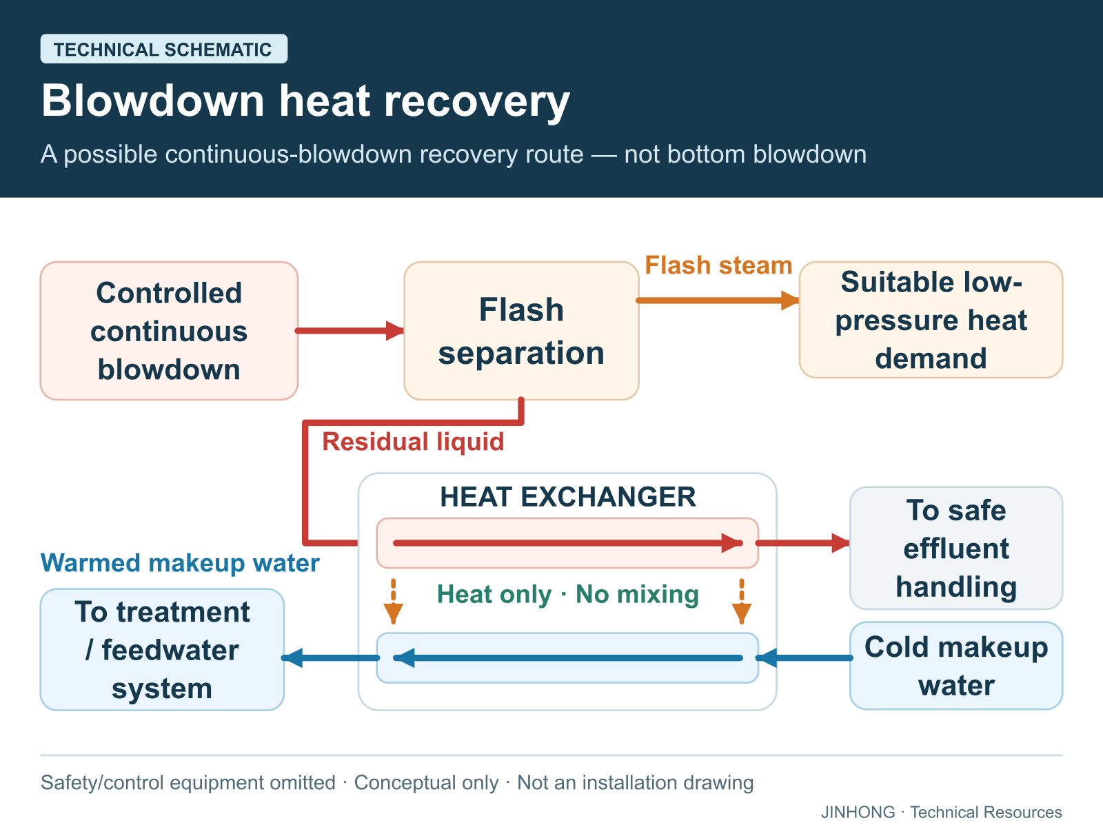
Open full-size technical schematic ↗
Boiler blowdown control is not simply a choice between saving water and keeping the boiler clean. It is a coordinated decision about water chemistry, steam quality, heat loss and safe disposal. An efficient arrangement removes the water needed to control contamination, avoids unnecessary discharge, and evaluates whether the remaining heat has a useful destination.
This guide concerns conventional industrial steam boilers. It is an assessment framework, not a valve-operating procedure or a substitute for the boiler manufacturer’s water-quality requirements.
Separate dissolved-solids control from sludge removal
As steam leaves a boiler, many nonvolatile substances remain in its water. Dissolved contaminants can contribute to foaming and carryover; suspended material can accumulate as deposits. Continuous or intermittent TDS blowdown manages dissolved-solids concentration, while bottom blowdown addresses settled material. Reducing either discharge without understanding its purpose can create a different operating problem. The DOE explains this balance between insufficient blowdown and excessive losses in its blowdown minimization guidance.
Start an assessment by identifying each discharge line on the approved piping diagram. A reading from a continuous-blowdown flowmeter does not necessarily include bottom-blowdown events. Similarly, a controller’s displayed operating time is not a measured water quantity.
Measure the right water before changing control
The feedwater entering the boiler may combine treated makeup water and returned condensate. Its dissolved-solids concentration is therefore not necessarily the same as the makeup-water analysis. Conductivity also depends on temperature and ionic composition, so a fixed conversion between conductivity and TDS should not be assumed for every treatment programme.
A representative sample, appropriate cooling arrangement and correctly configured conductivity measurement are essential. Spirax Sarco explains both sampling limitations and temperature compensation in its boiler-water TDS guidance. The allowable chemistry range must come from the boiler supplier and competent water-treatment specialist, taking operating pressure and steam-use requirements into account. Review our feedwater treatment basics for the wider system context.
An illustrative steady-state mass balance
A simple calculation helps explain the relationship between feedwater contamination and blowdown. It does not establish an operating limit.
Assume steady operation, negligible solids in exported steam, no deposition, and a conserved dissolved tracer that is not added or removed by chemical treatment. Let steam output be S, blowdown B, feedwater concentration Cf, and boiler-water concentration Cb. Water balance gives feedwater = S + B. Tracer balance gives (S + B)Cf = BCb, therefore:
B = S × Cf ÷ (Cb − Cf)
For an illustrative S of 4,000 kg/h, Cf of 100 mg/kg and assumed Cb of 2,000 mg/kg, B is approximately 211 kg/h. That is 5.26% of steam output but 5.00% of feedwater flow. These are different denominators, describing the same example.
The assumed concentrations are not recommended targets. Treatment reactions, variable condensate return, carryover and intermittent discharge can invalidate this simplified balance. Use it as a reasonableness check against measured plant data, not as a controller instruction.
Recover heat only where it can be used
Controlled pressure reduction can produce flash steam from hot blowdown water. An engineered flash vessel separates that steam from the remaining liquid; each stream may have a different recovery opportunity. The remaining liquid is still contaminated water, not automatically reusable feedwater. Spirax Sarco describes these distinctions in its blowdown heat-recovery explanation.
A heat exchanger can transfer useful heat into incoming makeup water. However, recoverable heat and usable heat are not identical: the receiving flow must be available when blowdown occurs. Compare hourly operating patterns, not just annual totals. The DOE’s heat-recovery tip sheet provides an assessment basis; its example recovery percentage is not a guaranteed value for another plant.
Estimate the proposal using the corrected blowdown requirement first. Then include exchanger fouling, pressure losses, maintenance access, receiving-water temperature, installed cost and actual operating hours. Counting today’s excessive blowdown as a permanent heat source can exaggerate the investment case.
Protect the discharge system
Bottom blowdown creates a rapid release of hot water, flash steam and reaction forces. Vessel capacity, piping support and discharge arrangements require engineering review. An average daily flow alone cannot describe the event. Spirax Sarco’s bottom-blowdown guidance explains why transient discharge conditions matter. Do not alter valve sequences, protective devices or discharge connections based on an energy calculation.
Practical assessment checklist
- Confirm boiler identification, operating conditions and approved chemistry limits.
- Compare representative feedwater, boiler-water and condensate records.
- Identify what each flowmeter measures and whether its units are comparable.
- Check conductivity calibration, compensation and sampling arrangements.
- Record both normal operation and bottom-blowdown events.
- Match recovery opportunities to simultaneous heat demand.
- Have competent personnel review vessel, piping and disposal requirements.
Frequently asked questions
Does automatic blowdown remove the need for water testing?
No. A controller manages its measured variable. Water chemistry, contamination and instrument condition still require verification under the approved treatment programme.
Can blowdown heat recovery justify increasing blowdown?
Not by itself. Establish the discharge needed for reliable boiler operation first, then recover useful heat from that flow.
Is there one ideal blowdown percentage?
No. It depends on the actual feedwater, treatment programme, boiler design and required steam purity. Always state whether a percentage refers to steam output or feedwater.
For a project discussion, share your boiler duty, water analysis and operating records. More equipment relationships are explained in our complete boiler-system overview.
Technical references
Primary sources consulted for this guide. Source publication dates and equipment contexts differ; historical examples are not JINHONG performance claims.