
THREE-PASS FIRE-TUBE STEAM BOILER
WNS Gas & Oil Fired Steam Boiler
Gas and oil-fired steam boilers from 0.5-20 t/h for industrial process steam. Share your process, available fuel and estimated demand to request a matched boiler quotation.
Start with your process, project country and email or phone. Leave unknown technical details blank. The burner and fuel system are selected for your actual gas or oil.
Tiếng Việt: tư vấn lò hơi WNSVietnamese enquiry guide · full technical information remains on this page.
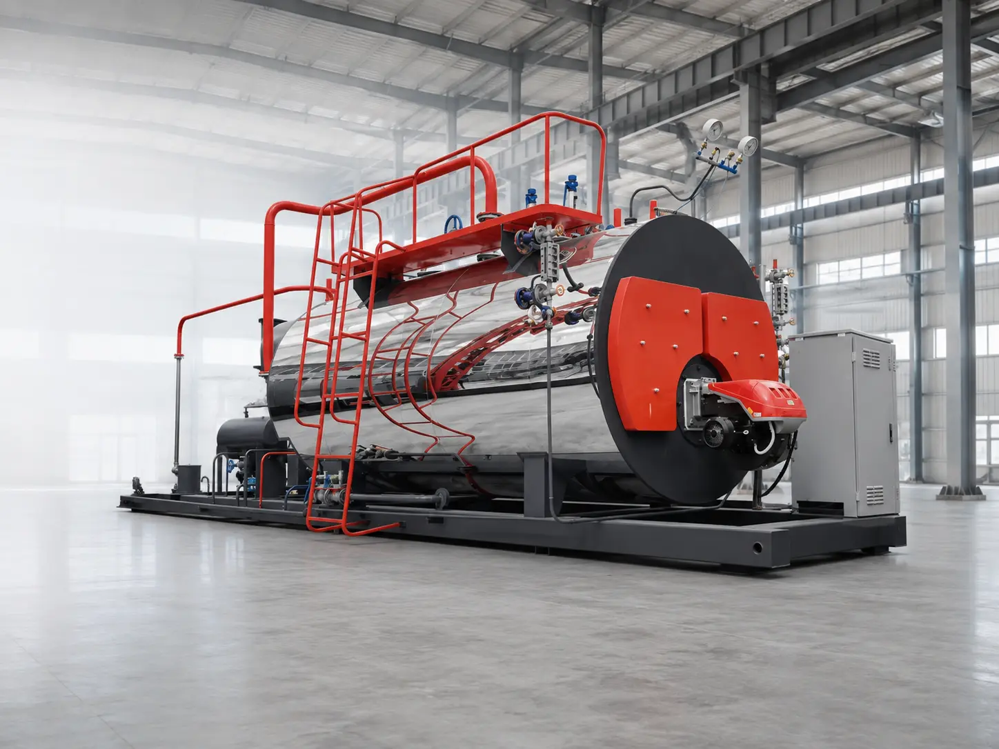
- Steam Capacity
- 0.5–20 t/h
- Rated Pressure
- 1.0–2.5 MPa
- Steam Type
- Saturated Steam
- Fuel Options
- Gas / Light Oil / Heavy Oil
TECHNICAL DATA
Reference Range for Initial Boiler Selection.
The table uses selected capacities from the JINHONG WNS technical data so the main page remains readable. Every available model and project-specific parameter is verified during proposal engineering.
| Model | Capacity t/h |
Available Rated Pressure MPa |
Natural Gas Consumption Nm³/h |
Light Oil Consumption kg/h |
Reference Dimensions L × W × H mm |
|---|---|---|---|---|---|
| WNS0.5 | 0.5 | 1.0 | 40 | 32 | 2900 × 1600 × 1900 |
| WNS1 | 1 | 1.25 | 72 | 61 | 3650 × 1950 × 2200 |
| WNS2 | 2 | 1.0 / 1.25 / 1.6 / 2.5 | 158 | 120 | 4650 × 2100 × 2450 |
| WNS4 | 4 | 1.0 / 1.25 / 1.6 / 2.5 | 313 | 243 | 4800 × 2300 × 2800 |
| WNS6 | 6 | 1.0 / 1.25 / 1.6 / 2.5 | 452 | 354 | 6300 × 2700 × 2900 |
| WNS10 | 10 | 1.25 / 1.6 / 2.5 | 770 | 580 | 7400 × 3730 × 3530 |
| WNS20 | 20 | 1.25 / 1.6 / 2.5 | 1330 | 1157 | 10000 × 4500 × 5600 |
Use the gas and diesel fuel-consumption comparison guide to compare steam duty, fuel units and fuel-only cost on a stated calculation basis.
Fuel basis: natural gas consumption is calculated at a lower heating value of 35,588 kJ/Nm³; light oil at 42,700 kJ/kg.
Selection note: consumption changes with fuel quality, actual load, feedwater temperature, steam pressure, burner adjustment and heat-recovery arrangement. Dimensions and all parameters are reference values; approved drawings and the final technical agreement take precedence.
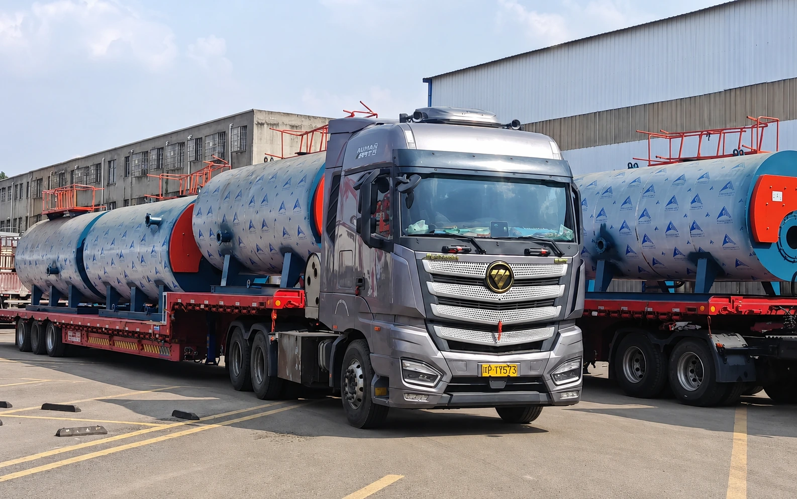
COMPLETE SYSTEM SCOPE
The Boiler Is One Part of the Steam System.
A workable proposal defines how the boiler body connects to combustion, feedwater, controls, heat recovery, flue-gas routing and the customer’s existing plant utilities.
Not every item is included by default. The final supply scope, component brands, documentation and site interface are stated in the approved proposal.
View the WNS skid-package project record.
Define your system boundaryPRODUCT OVERVIEW
A Compact Boiler Route for Reliable Industrial Steam.
The WNS series is a horizontal shell-type fire-tube boiler. Its furnace and smoke tubes are surrounded by boiler water, while the three-pass flue-gas route transfers combustion heat through the pressure-bearing heating surfaces.
The packaged arrangement is suited to plants that require a defined steam output, compact boiler-room planning and coordinated burner, controls and auxiliaries.
Packaged Fire-Tube Structure
The boiler body, front and rear smoke boxes, burner interface and main safety/control points are organized as one engineered package.
Three-Pass Wet-Back Route
Combustion gas travels through the furnace and subsequent smoke-tube passes before reaching the flue outlet and optional heat recovery.
Matched to the Real Load
Capacity, working pressure, fuel, burner modulation and auxiliaries are confirmed from the plant’s steam-demand profile.
Engineered as a System
Feedwater, water treatment, controls, heat recovery, flue system and documentation are defined within the agreed supply boundary.
HOW THE WNS BOILER WORKS
Three Heat-Transfer Passes in a Fully Wet-Back Shell.
The burner fires into the large internal furnace, forming the first pass. The rear wet-back chamber turns the flue gas into the second and third smoke-tube passes, transferring heat to the surrounding boiler water before the gas leaves the boiler.
An economizer or condensing recovery section can be evaluated after the fuel, return-water or feedwater conditions, flue-gas route and project requirements are confirmed.
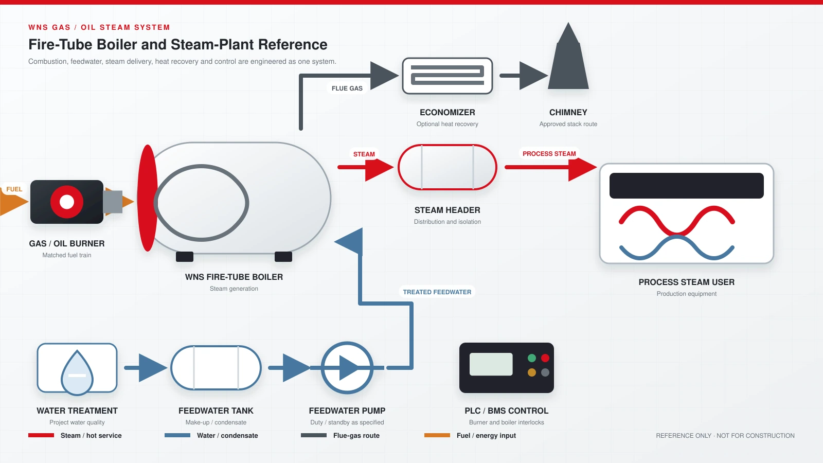
REFERENCE SYSTEM DIAGRAM
How the WNS Boiler Connects to the Complete Steam Plant.
The diagram organizes combustion, steam distribution, feedwater treatment, heat recovery, flue-gas discharge and plant controls around the packaged fire-tube boiler.
DESIGN FEATURES
Designed Around Heat Transfer, Steam Stability and Maintainability.
These design points describe the current JINHONG WNS product route. The construction and component brands used for a project are confirmed in the approved technical proposal.
01 / STRUCTURE
Fully Wet-Back Construction
The rear reversal chamber is surrounded by boiler water, supporting effective heat transfer within the shell structure.02 / COMBUSTION
Large Combustion Chamber
The furnace volume supports appropriate flame development; burner selection is matched to fuel and operating requirements.03 / HEAT TRANSFER
Helical Smoke Tubes
The smoke-tube arrangement increases effective heat-transfer surface and guides flue gas through the return passes.04 / SEALING
Multi-Stage Smoke-Box Sealing
Front and rear smoke-box interfaces use coordinated sealing to control flue-gas leakage and support routine inspection.05 / OPERATION
Steam Space and Protection Points
Water level, steam pressure and flue-gas temperature monitoring are coordinated with alarms and operating interlocks.06 / SERVICE
Maintenance-Oriented Details
Movable smoke-box covers, inspection points and multi-point drainage support cleaning and planned maintenance access.INDUSTRIAL APPLICATIONS
Steam Supply Built Around the Production Process.
The same nominal boiler capacity can behave differently across industries. Selection must account for peak load, operating hours, pressure loss, condensate return and process variability.
Textile & Dyeing
Steam for dyeing, washing, drying, finishing and related process-heating duties.
Explore solution →Food & Beverage
Process steam for cooking, sterilization, cleaning and temperature-controlled production.
Explore solution →Chemical Processing
Stable steam supply for reactors, heat exchangers, tanks and production-line utilities.
Explore solution →Paper & Corrugating
Steam for drying cylinders, corrugating lines, starch preparation and plant heating loads.
Explore solution →Laundry & Garment Care
Central steam for washers, dryers, ironing equipment and continuous laundry operations.
Explore solution →Metal & General Manufacturing
Process steam for cleaning, surface treatment, baths and supporting production utilities.
Explore solution →Planning a dyeing-line expansion? Review the steam capacity and pressure checks.
SELECTION INPUTS
Send the Process Data Before Selecting a Model.
Approximate information is acceptable for the first review. JINHONG engineers will use it to establish an initial capacity, pressure, fuel and system direction.
- 01Steam Demand
Average load, peak load and daily operating hours.
- 02Working Pressure
Required pressure at the boiler outlet and at the process point.
- 03Fuel Conditions
Fuel type, lower heating value, supply pressure and local availability.
See a 6 TPH natural-gas WNS installation in Egypt
Natural-gas steam supply for textile dyeing, completed in 2024.
- 04Feedwater & Condensate
Water quality, inlet temperature and expected condensate-return ratio.
- 05Site & Utilities
Boiler-room space, altitude, power supply, transport and installation limits.
- 06Project Boundary
Required auxiliaries, controls, documentation and installation support.
TECHNICAL FAQ
Common Questions About WNS Boiler Selection.
What information is needed for a WNS boiler quotation?
Share your steam demand, working pressure, available fuel and project location. Burner selection, auxiliaries and supply scope are confirmed in the project proposal. Unknown details can be left blank for the initial enquiry.
What capacity range is available for the JINHONG WNS series?
The current technical range covers 0.5 to 20 t/h of rated saturated-steam capacity. The appropriate model is selected from the actual average demand, peak demand and operating profile.
Which fuels can a WNS boiler use?
The current range supports gaseous fuel, light oil and heavy oil routes. The burner, fuel train, storage or supply interface and controls must be selected for the actual fuel specification.
What working pressure is available?
The WNS product range covers rated working pressures from 1.0 to 2.5 MPa, with available pressure options varying by capacity. Final pressure is confirmed against the process requirement and applicable design documents.
Can an economizer or condensing recovery unit be added?
Yes, heat recovery can be evaluated when the fuel, flue-gas conditions, feedwater or return-water temperature, chimney route and project economics are suitable.
Why can actual fuel consumption differ from the table?
The listed values use fixed lower-heating-value assumptions. Actual consumption changes with fuel quality, boiler load, feedwater temperature, steam pressure, burner tuning, blowdown and heat-recovery configuration.
When should a water-tube boiler be considered instead?
A water-tube route may be reviewed when the required capacity, pressure, load changes, redundancy or site conditions move beyond the preferred packaged fire-tube solution. The comparison should be made from project data rather than model name alone.
WNS TECHNICAL PROPOSAL