
ATMOSPHERIC GAS / OIL HOT WATER BOILER
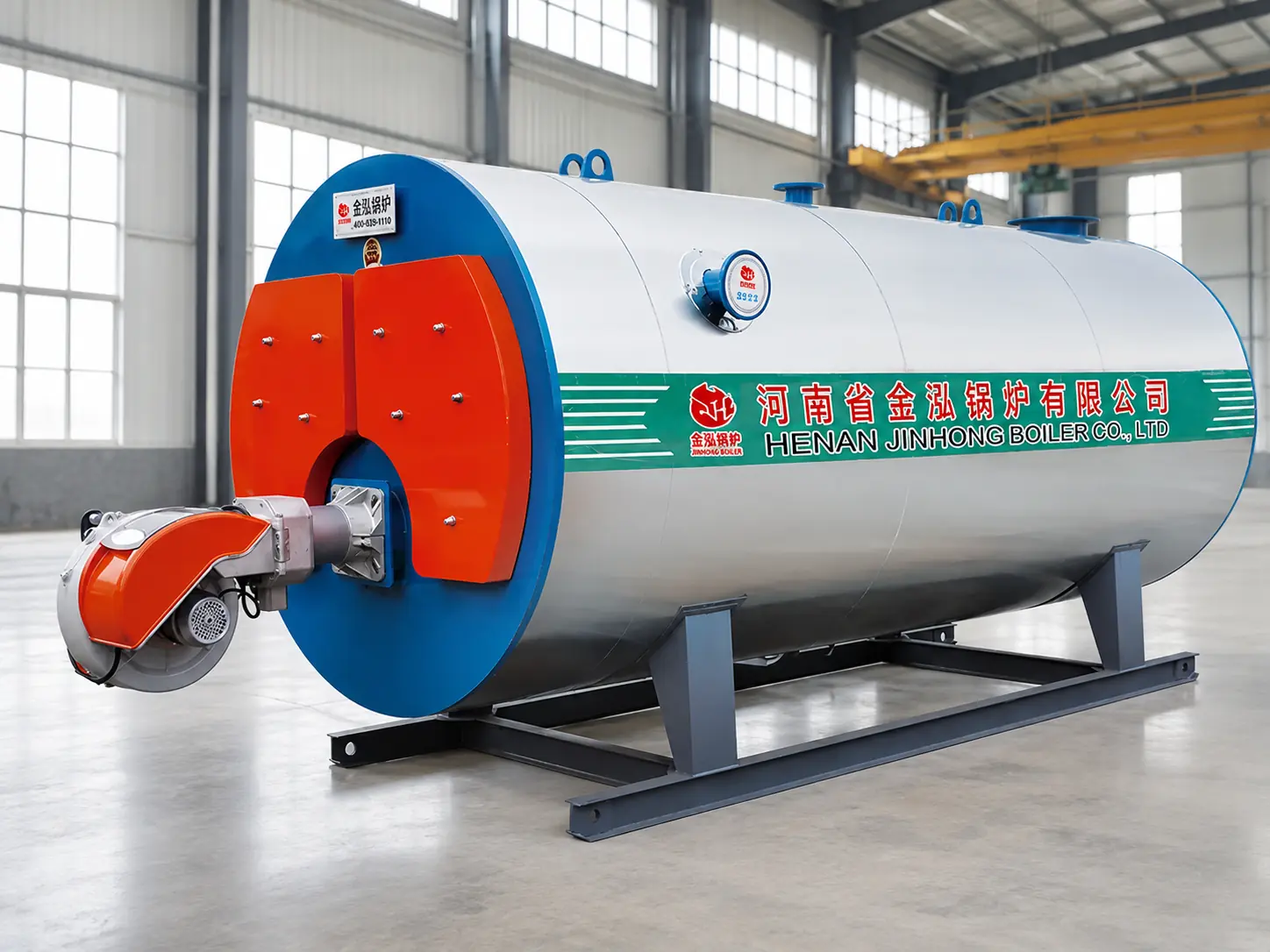
CWNS Gas/Oil Hot Water Boiler
Horizontal hot-water boiler systems engineered around the real heating load, supply and return temperatures, fuel conditions, circulation route, expansion arrangement and customer-side interfaces.
- Heating Capacity
- 20–900 × 104 kcal/h
- Outlet / Return Water Temperatures
- 85 / 60°C
- Thermal Efficiency
- 93%
- Fuel Routes
- Gas / Oil
PRODUCT OVERVIEW
Hot-Water Generation Defined as a Complete Circulation System.
The CWNS series is a horizontal, gas- or oil-fired atmospheric hot-water boiler. A matched burner releases heat inside the furnace, flue gas transfers energy through the boiler heating surfaces, and the circulation system delivers hot water to the plant load.
Because the boiler route is atmospheric, expansion, venting and system separation must be deliberately defined. The boiler can serve a compatible open circuit directly or connect to a closed customer circuit through a plate heat exchanger, subject to the approved project design and local requirements.
Atmospheric Boiler Route
The boiler-side circuit is kept open to atmosphere through an approved expansion and venting arrangement.
Gas or Oil Combustion
The burner and fuel train are selected from the approved fuel, capacity, emissions target and local supply conditions.
Direct or Separated Load
A compatible load may use the boiler circuit directly, while a plate heat exchanger can hydraulically separate another circuit.
Engineered Plant Boundary
Pumps, water treatment, expansion, heat recovery, controls, chimney and customer interfaces are defined together.
COMBUSTION & WATER CIRCUIT
One Coordinated Route from Fuel Input to Useful Hot Water.
The matched burner mixes fuel and combustion air, then fires into the horizontal furnace. Heat is transferred to the boiler water while flue gas passes through the designed heating route and exits through the selected economizer and chimney arrangement.
The circulation pump moves heated water to the load and returns cooled water to the boiler. Water quality, minimum circulation, expansion, venting, low-water protection and burner interlocks must be coordinated before firing.
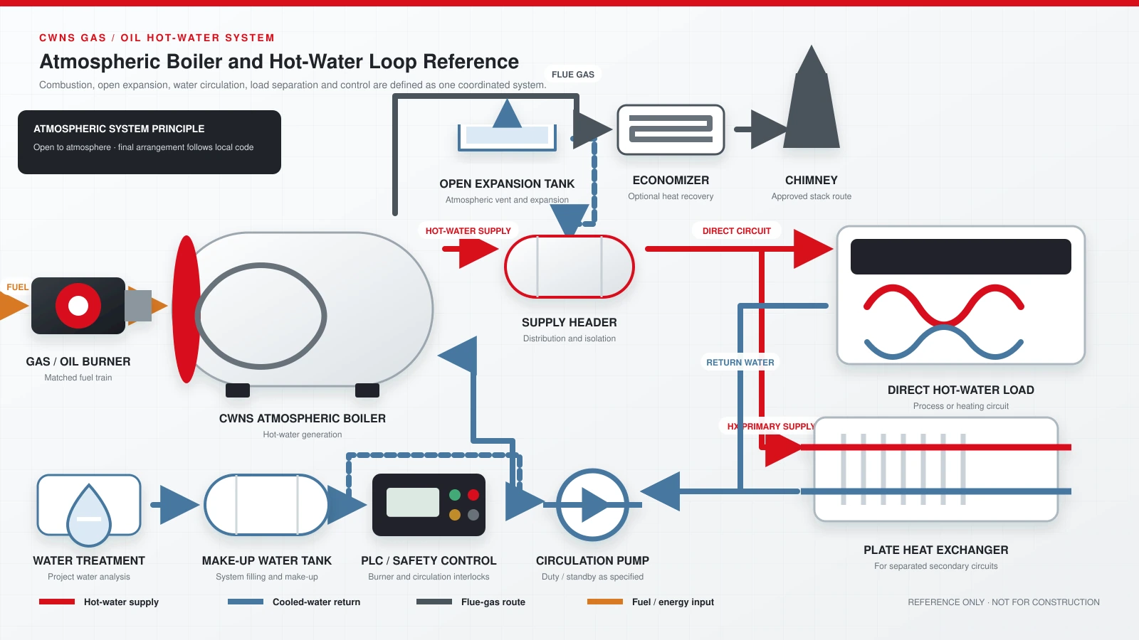
REFERENCE SYSTEM DIAGRAM
How the CWNS Boiler Connects to the Hot-Water Plant.
This simplified diagram shows the main equipment and flow direction for discussion. Final pipe sizes, elevations, expansion, valves, instruments, redundancy, heat recovery, local-code provisions and control points follow the approved calculations and drawings.
DESIGN FEATURES
Designed for Heat Transfer, Automatic Control and Practical Maintenance.
Horizontal Three-Pass Route
The CWNS product range describes a three-pass arrangement designed to increase effective heat transfer within a compact boiler body.
Corrugated Furnace
The corrugated furnace supports heat-transfer area and accommodates thermal expansion in the firing chamber.
Insulated Boiler Body
Aluminum-silicate insulation is specified in the CWNS product range to reduce external surface heat loss.
Matched Burner Package
Burner output, turndown, fuel train and emissions option are selected from the approved fuel and operating requirement.
Water & Temperature Protection
Low-water, over-temperature and circulation conditions are coordinated with burner permissives and shutdown logic.
Automatic System Control
The controller can coordinate combustion, make-up water and circulation functions within the agreed control boundary.
TECHNICAL DATA
Representative CWNS Models from the JINHONG CWNS product range.
The table reproduces selected values from the JINHONG 2026 product catalogue, printed page 22, for initial discussion. Final capacity, burner, pump, water circuit, heat recovery and overall arrangement must be confirmed against the actual project duty and approved technical proposal.
| Model | CWNS0.24-85/60-YQ | CWNS0.7-85/60-YQ | CWNS1.4-85/60-YQ | CWNS2.8-85/60-YQ | CWNS4.2-85/60-YQ | CWNS7.0-85/60-YQ | CWNS10.5-85/60-YQ |
|---|---|---|---|---|---|---|---|
| Rated Heating Capacity × 104 kcal/h | 20 | 60 | 120 | 240 | 360 | 600 | 900 |
| Outlet Water Temperature °C | 85 | 85 | 85 | 85 | 85 | 85 | 85 |
| Return Water Temperature °C | 60 | 60 | 60 | 60 | 60 | 60 | 60 |
| Thermal Efficiency % | 93 | 93 | 93 | 93 | 93 | 93 | 93 |
| Natural Gas Consumption m³/h | 28.6 | 85.7 | 171.4 | 342.9 | 514.3 | 857.1 | 1,285.7 |
| Light Oil Consumption kg/h | 23.5 | 70.6 | 141.2 | 282.4 | 423.5 | 705.9 | 1,058.8 |
| Power Consumption kW | 4 | 7 | 11 | 24 | 43 | 70 | 84 |
| Reference Voltage V | 220 | 380 | 380 | 380 | 380 | 380 | 380 |
| Transport Weight t | 1.9 | 3.0 | 4.1 | 7.5 | 9.2 | 18.7 | 25 |
| Reference Overall Size L × W × H, mm | 2500 × 1060 × 1450 | 3000 × 1360 × 1800 | 3600 × 1660 × 2100 | 4700 × 2000 × 2400 | 5800 × 2100 × 2500 | 6800 × 2600 × 3100 | 8000 × 2700 × 3200 |
Fuel basis: The technical data use lower heating values of 8,400 kcal/Nm³ for natural gas, 10,500 kcal/Nm³ for LPG, 4,000 kcal/Nm³ for city gas, 10,200 kcal/kg for light oil and 10,000 kcal/kg for heavy oil.
Fuel consumption: Reference only. Actual use varies with the delivered fuel, operating load, excess air, water temperatures, ambient conditions, heat recovery, circulation route and system losses.
Catalogue efficiency reference: The original catalogue lists 93% thermal efficiency. Confirm the efficiency definition, heating-value basis and test conditions in the project technical agreement. The listed fuel-consumption figures are also catalogue reference values; final performance follows the agreed project conditions.
Dimensions and weight: Reference only. Use the approved general-arrangement drawing for transport, lifting, foundation, boiler-room access and maintenance planning.
FUEL & BURNER ENGINEERING
Select the Burner from the Actual Fuel Supply and Operating Target.
Gas and oil names alone are not sufficient. A reliable proposal requires the real fuel composition or heating value, supply pressure and temperature, required turndown, local emissions limit, electrical standard and expected load profile.
Send fuel and heating data- 01Natural Gas
Provide composition or lower heating value, inlet pressure, available flow and required pressure regulation.
- 02LPG or City Gas
Different heating values and supply characteristics change burner sizing, fuel-train components and consumption.
- 03Light or Heavy Oil
Viscosity, temperature, storage, filtration, pumping and atomization requirements must be confirmed.
- 04Burner Turndown
The burner should follow the expected load profile without excessive cycling at low demand.
For load-matching guidance, review boiler turndown and short-cycling control. The required burner range and sequencing logic must be confirmed from the project load profile.
- 05Emissions Target
Local NOx and other applicable limits must be stated before the burner and heat-recovery route are finalized.
- 06Site Standard
Confirm voltage, frequency, altitude, ambient temperature, fuel standard and destination-code requirements.
BOILER & SYSTEM BOUNDARY
A Complete Hot-Water Plant Extends Beyond the Boiler Body.
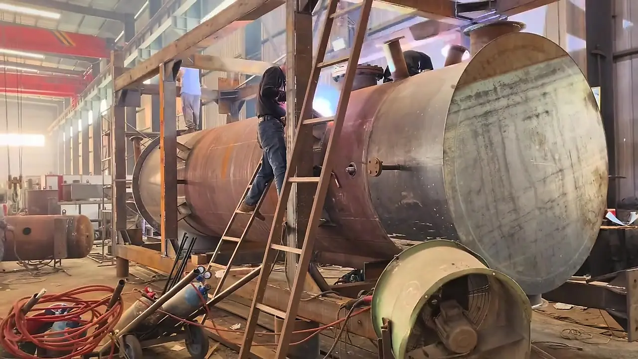
The boiler must be coordinated with the burner and fuel train, circulation pumps, expansion and venting, make-up water, water treatment, heat exchanger where required, heat recovery, chimney, electrical control and every customer-side connection.
Plant piping, customer pumps, building terminals, heat exchangers, civil works, installation, local approvals and utilities are included only when explicitly listed in the agreed supply scope.
Define the system boundaryAPPLICATIONS
Hot Water for Heating and Compatible Industrial Processes.
Application suitability depends on the useful heat load, required temperatures, circuit type, water quality, operating schedule and local requirements—not industry name alone.
Industrial Space Heating
Factory, warehouse and workshop heating through a compatible circulation or separated terminal-water circuit.
Hotels & Commercial Buildings
Central heating and domestic-hot-water preparation through an approved heat-exchanger and hygiene design.
Hospitals & Campuses
Building heating and service-water preparation where separation, redundancy and operating schedules are defined.
Food & Beverage Plants
Cleaning, washing and indirect process heating through a suitable sanitary or process heat exchanger.
Textile & Laundry Facilities
Washing, hot-water preparation and space heating subject to actual temperature and peak-demand profiles.
Greenhouses & Agricultural Heating
Low-temperature distribution circuits sized from climate, growing area, envelope losses and control zones.
SELECTION GUIDANCE
Select the Boiler from the Heat Balance and the Real Water Circuit.
A dependable proposal separates normal and peak duty, verifies design temperatures and flow, then defines the open boiler-side route, any separated customer circuit, fuel input, pump head, heat loss and redundancy.
Review industry solutions- 01Useful Heat Load
Provide normal and peak kW or kcal/h, operating hours and simultaneous demand instead of floor area alone.
- 02Supply & Return Temperatures
The approved temperature difference determines circulation flow, heat-transfer area and pump selection.
- 03Direct or Separated Circuit
Confirm whether the load can use the atmospheric boiler circuit or requires a plate heat exchanger.
- 04Water Quality & Make-Up
Send raw-water analysis, make-up rate and expected leakage so the treatment route can be defined.
- 05Fuel & Emissions
Provide fuel data, inlet conditions, operating profile and the applicable emissions requirements.
- 06Site Conditions
Confirm altitude, ambient temperature, power supply, boiler-room access, chimney route and destination codes.
CUSTOMER PROJECT · VIETNAM 2026
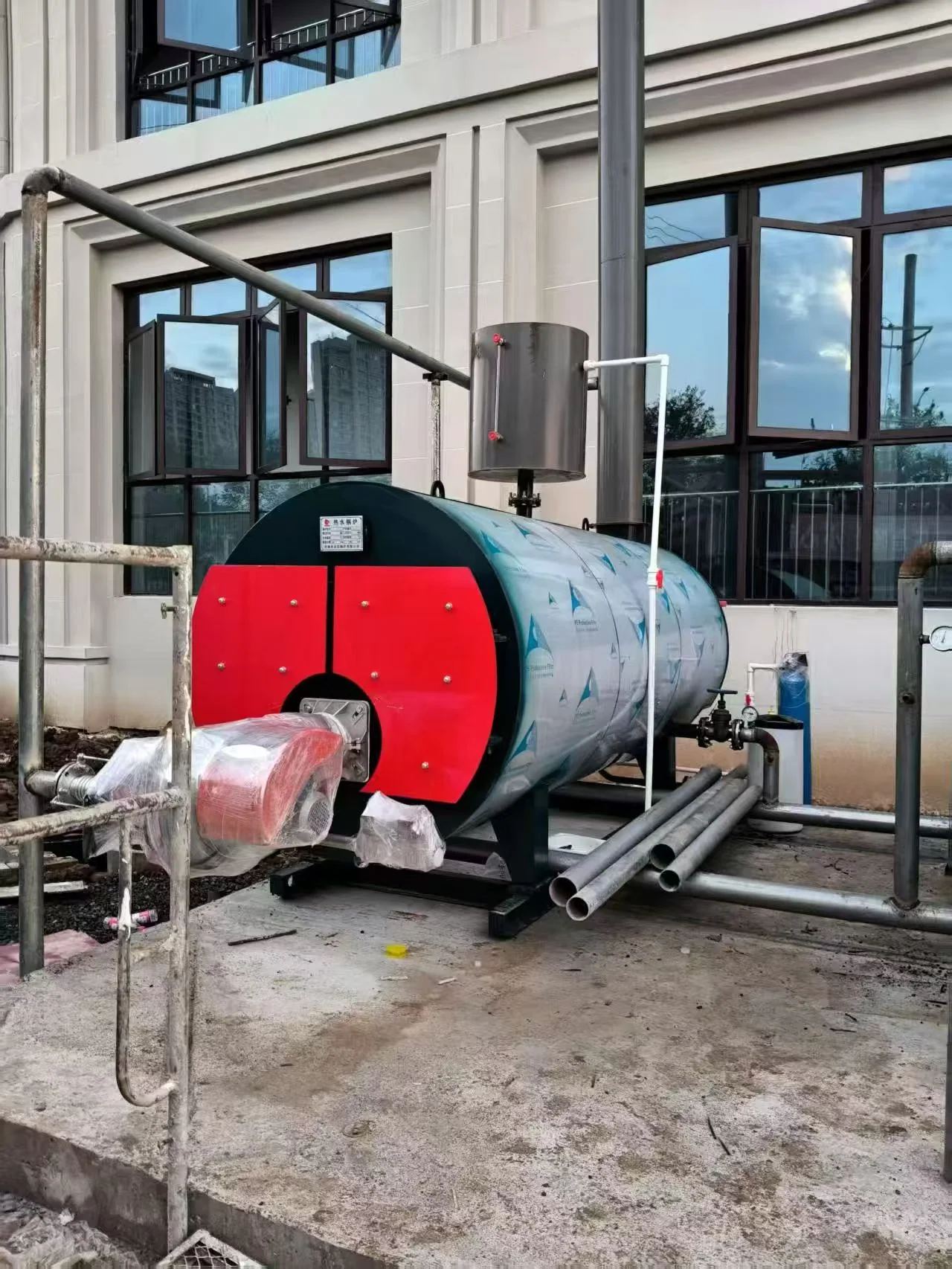
Two 1.4 MW CWNS Boilers for Building Heating.
This delivered project uses two CWNS atmospheric natural gas hot water boilers for building space heating, providing 2.8 MW of total installed rated output at 85/60°C. The supplied arrangement includes automatic startup, shutdown and rotation, while JINHONG engineers guided the on-site installation.
- 2 × 1.4 MW
- 85 / 60°C
- Natural Gas
- Delivered and In Use
FREQUENTLY ASKED QUESTIONS
CWNS Gas/Oil Hot Water Boiler FAQ.
What capacity range is listed for the JINHONG CWNS series?
The JINHONG CWNS product range lists model designations from 0.24 to 10.5 MW, with rated heating-capacity values from 20 to 900 × 104 kcal/h. Final selection follows the project heat balance and system losses.
What do the 85/60°C values mean?
They are the outlet and return water temperatures listed in the current CWNS model table. Other project temperatures require engineering review because they change water flow, heat-transfer conditions, pump duty and system performance.
Is the CWNS boiler a pressurized hot-water boiler?
The CWNS series described here is an atmospheric hot-water boiler. The boiler-side circuit must retain an approved open expansion and vent route. A closed customer circuit can be separated through a heat exchanger where appropriate.
Can one burner operate on both gas and oil?
A dual-fuel burner can be evaluated when both fuels and changeover requirements are defined. It is not assumed by the boiler model name; the approved burner, fuel trains, controls and scope must state the selected arrangement.
Is the technical data fuel-consumption value guaranteed?
No. It is a reference based on the stated fuel heating value and technical data conditions. Actual consumption depends on delivered fuel, operating load, tuning, water temperatures, heat recovery, ambient conditions and the agreed test boundary.
What is normally included in a complete CWNS system?
The defined package may include the boiler, burner and fuel train, circulation pumps, expansion and venting, water treatment, make-up tank, headers, controls, economizer, heat exchanger and chimney. Only the approved proposal defines final supply.
What information is needed for a technical proposal?
Send normal and peak heat load, supply and return temperatures, application, operating hours, direct or separated circuit preference, water analysis, fuel data, emissions target, power supply, altitude, destination and required scope.
START WITH HEAT-LOAD & CIRCUIT DATA
Get a CWNS Proposal Matched to Your Load, Fuel and Hot-Water System.
Send the normal and peak heat demand, supply and return temperatures, application, operating hours, circuit arrangement, water analysis, fuel data, emissions target and destination. JINHONG will define the boiler and complete system boundary for technical review.