
INDUSTRIAL PROCESS AIR HEATING
WRF, ZRFQ & LRF Hot Air Furnaces
Three engineered routes for clean indirect air, direct mixed hot gas and biomass-fired indirect process heating.
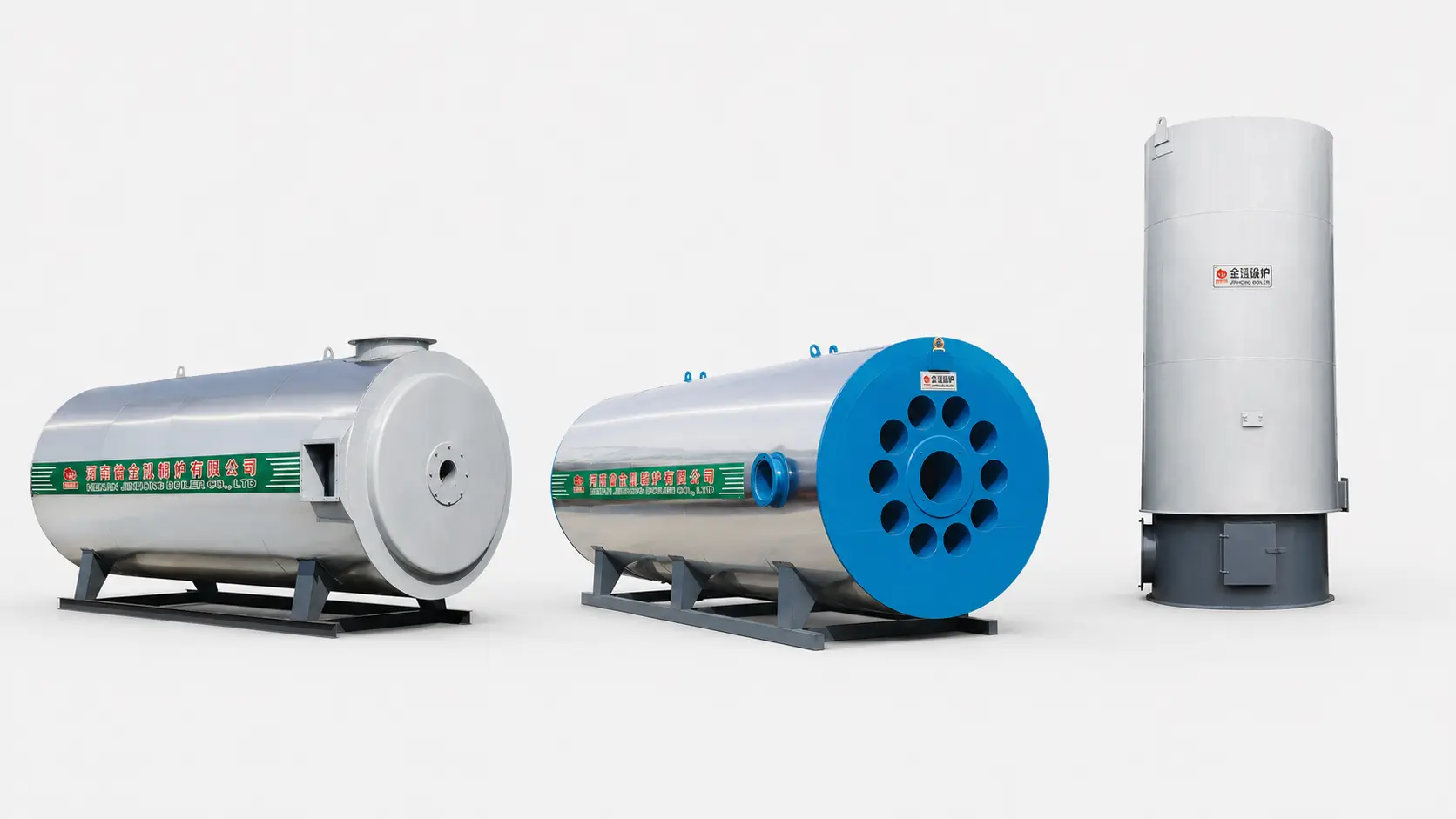
- Rated Power
- 0.12-7.2 MW
- Outlet Temperature
- Up to 800°C
- Fuel Routes
- Gas / Oil / Biomass
- Heating Routes
- Indirect / Direct
PRODUCT FAMILY OVERVIEW
Select the Air Quality Route Before Selecting the Furnace Size.
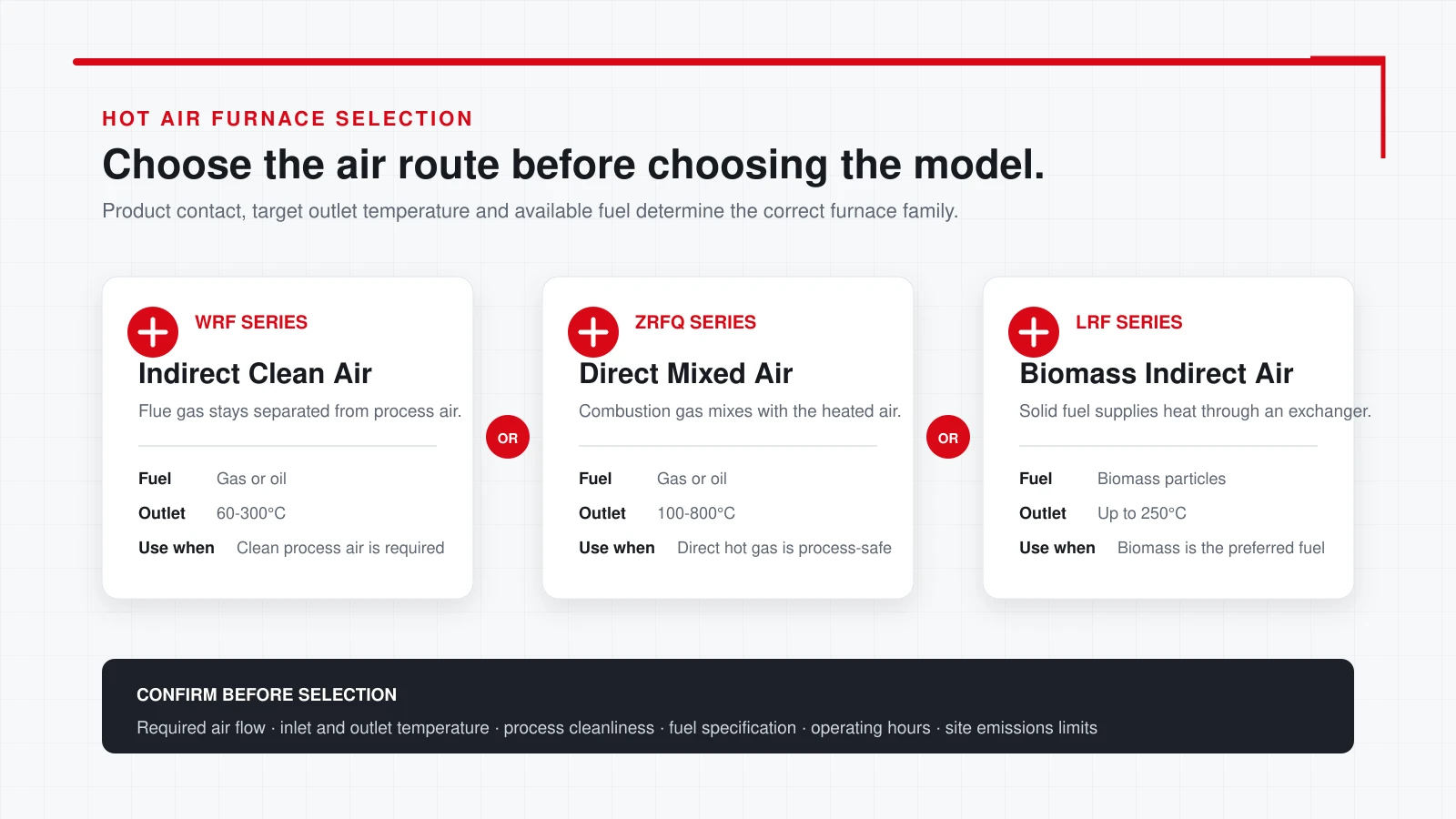
A hot air furnace must match more than the required temperature. The key decision is whether combustion gas may contact the process air or whether the heated air must remain separated through a heat exchanger.
After the air route is fixed, the model is selected from the real air volume, inlet and outlet temperatures, product moisture load, operating hours, fuel specification and site emissions requirements.
WRF Clean Air
Gas or oil combustion with indirect heat exchange for process air separated from flue gas.
ZRFQ Mixed Air
Direct combustion for higher outlet temperature where combustion products are acceptable in the process stream.
LRF Biomass Air
Biomass-fired indirect heating for projects that prioritize solid fuel and separated process air.
System Engineered
Fans, burner or feeding equipment, controls, ducting and emissions equipment are matched to the selected route.
SERIES SELECTION
Clean Air, Direct Hot Gas or Biomass-Fired Indirect Air.
Confirm whether the heated air contacts food, textiles, coatings, timber or other process materials before choosing the direct or indirect route.
WRF SERIES / INDIRECT CLEAN AIR
Gas or Oil Heating with Flue Gas Separated from Process Air.
The WRF horizontal furnace transfers heat through a multi-pass heat-exchange structure. Combustion gas and process air follow separated routes, supporting applications where the delivered hot air must remain free from direct combustion products.
The published range covers 0.12-3.5 MW, 60-300°C outlet temperature and 86% thermal efficiency. Burner, fuel train, control logic, fan duty and materials are confirmed against the selected fuel and process conditions.
WRF TECHNICAL DATA
WRF Indirect Clean-Air Furnace Range.
Fuel consumption is calculated on the listed standard lower heating values. Final consumption follows the actual fuel analysis, operating load, excess air and agreed test conditions.
| Model | Rated Power (MW) | Outlet Range (°C) | Efficiency | Natural Gas (m³/h) | LPG (m³/h) | City Gas (m³/h) | Light Diesel (kg/h) | Heavy Oil (kg/h) |
|---|---|---|---|---|---|---|---|---|
| WRF-10-YQ | 0.12 | 60-300 | 86% | 15 | 12 | 33 | 13 | 13 |
| WRF-20-YQ | 0.24 | 60-300 | 86% | 31 | 25 | 65 | 25 | 26 |
| WRF-30-YQ | 0.35 | 60-300 | 86% | 46 | 37 | 98 | 38 | 39 |
| WRF-40-YQ | 0.49 | 60-300 | 86% | 62 | 50 | 130 | 51 | 52 |
| WRF-60-YQ | 0.70 | 60-300 | 86% | 93 | 74 | 195 | 76 | 78 |
| WRF-80-YQ | 1.05 | 60-300 | 86% | 124 | 99 | 260 | 102 | 104 |
| WRF-100-YQ | 1.20 | 60-300 | 86% | 155 | 124 | 325 | 127 | 130 |
| WRF-120-YQ | 1.40 | 60-300 | 86% | 186 | 149 | 390 | 153 | 156 |
| WRF-150-YQ | 1.70 | 60-300 | 86% | 232 | 186 | 488 | 191 | 195 |
| WRF-180-YQ | 2.10 | 60-300 | 86% | 279 | 223 | 585 | 229 | 234 |
| WRF-200-YQ | 2.40 | 60-300 | 86% | 310 | 248 | 650 | 255 | 260 |
| WRF-240-YQ | 2.80 | 60-300 | 86% | 371 | 297 | 780 | 306 | 312 |
| WRF-300-YQ | 3.50 | 60-300 | 86% | 464 | 371 | 975 | 382 | 390 |
Calculation basis: Natural gas 8,400 kcal/Nm³; LPG 10,500 kcal/Nm³; city gas 4,000 kcal/Nm³; light diesel 10,200 kcal/kg; heavy oil 10,000 kcal/kg.
Dimensions and weight: Confirm from the approved general-arrangement drawing for the selected burner, fan, heat-exchange structure and site interface.
ZRFQ SERIES / DIRECT MIXED AIR
High-Temperature Direct Heating Where Combustion Gas Is Acceptable.
The ZRFQ horizontal furnace mixes controlled combustion gas with the heated-air stream. Eliminating the separating heat exchanger supports a compact route, faster response and a higher listed temperature range.
The published range covers 0.12-7.2 MW, 100-800°C outlet temperature and 98% thermal efficiency. This route is selected only after the process owner confirms that direct combustion products are acceptable for the material, equipment and local rules.
ZRFQ TECHNICAL DATA
ZRFQ Direct Mixed-Air Furnace Range.
Direct-fired suitability must be confirmed against product safety, air-quality limits, material sensitivity and the customer’s process standard.
| Model | Rated Power (MW) | Outlet Range (°C) | Efficiency | Natural Gas (m³/h) | LPG (m³/h) | City Gas (m³/h) | Light Diesel (kg/h) | Heavy Oil (kg/h) |
|---|---|---|---|---|---|---|---|---|
| ZRFQ-10-YQ | 0.12 | 100-800 | 98% | 14 | 11 | 30 | 12 | 12 |
| ZRFQ-20-YQ | 0.24 | 100-800 | 98% | 29 | 23 | 60 | 24 | 24 |
| ZRFQ-30-YQ | 0.35 | 100-800 | 98% | 43 | 34 | 90 | 35 | 36 |
| ZRFQ-40-YQ | 0.49 | 100-800 | 98% | 57 | 46 | 120 | 47 | 48 |
| ZRFQ-60-YQ | 0.70 | 100-800 | 98% | 86 | 69 | 180 | 71 | 72 |
| ZRFQ-80-YQ | 1.05 | 100-800 | 98% | 114 | 91 | 240 | 94 | 96 |
| ZRFQ-100-YQ | 1.20 | 100-800 | 98% | 143 | 114 | 300 | 118 | 120 |
| ZRFQ-120-YQ | 1.40 | 100-800 | 98% | 171 | 137 | 360 | 141 | 144 |
| ZRFQ-150-YQ | 1.70 | 100-800 | 98% | 214 | 171 | 450 | 176 | 180 |
| ZRFQ-180-YQ | 2.10 | 100-800 | 98% | 257 | 206 | 540 | 212 | 216 |
| ZRFQ-200-YQ | 2.40 | 100-800 | 98% | 286 | 229 | 600 | 235 | 240 |
| ZRFQ-240-YQ | 2.80 | 100-800 | 98% | 343 | 274 | 720 | 282 | 288 |
| ZRFQ-300-YQ | 3.50 | 100-800 | 98% | 429 | 343 | 900 | 353 | 360 |
| ZRFQ-360-YQ | 4.20 | 100-800 | 98% | 514 | 411 | 1080 | 424 | 432 |
| ZRFQ-480-YQ | 5.60 | 100-800 | 98% | 686 | 549 | 1440 | 565 | 576 |
| ZRFQ-600-YQ | 7.20 | 100-800 | 98% | 857 | 686 | 1800 | 706 | 720 |
Calculation basis: Natural gas 8,400 kcal/Nm³; LPG 10,500 kcal/Nm³; city gas 4,000 kcal/Nm³; light diesel 10,200 kcal/kg; heavy oil 10,000 kcal/kg.
Process boundary: Direct-fired air must be accepted by the process owner. Confirm emissions, odor, product contact and safety requirements before selection.
LRF SERIES / BIOMASS INDIRECT AIR
Vertical Biomass Heating with an Integrated Indirect Air Route.
The LRF series integrates the combustion chamber and heat-exchange structure in a vertical arrangement. Process air and flue gas follow separated passages while heat is transferred through the configured multi-pass surface.
The published range covers 0.12-2.4 MW, outlet temperature up to 250°C and 83.5% thermal efficiency. The listed fuel consumption uses biomass particles at 4,000 kcal/kg; actual fuel form, moisture, ash and feeding method must be reviewed.
LRF TECHNICAL DATA
LRF Biomass Indirect Hot-Air Furnace Range.
Fuel consumption is based on biomass particles with a lower heating value of 4,000 kcal/kg. Recalculate for the actual fuel before the technical proposal is finalized.
| Model | Rated Power (MW) | Maximum Outlet Temperature | Efficiency | Biomass Consumption (kg/h) |
|---|---|---|---|---|
| LRF-10-SC II | 0.12 | ≤250°C | 83.5% | 32.5 |
| LRF-20-SC II | 0.24 | ≤250°C | 83.5% | 65 |
| LRF-30-SC II | 0.35 | ≤250°C | 83.5% | 97.5 |
| LRF-40-SC II | 0.49 | ≤250°C | 83.5% | 130 |
| LRF-60-SC II | 0.70 | ≤250°C | 83.5% | 195 |
| LRF-80-SC II | 1.05 | ≤250°C | 83.5% | 260 |
| LRF-100-SC II | 1.20 | ≤250°C | 83.5% | 325 |
| LRF-120-SC II | 1.40 | ≤250°C | 83.5% | 390 |
| LRF-150-SC II | 1.70 | ≤250°C | 83.5% | 487.5 |
| LRF-180-SC II | 2.10 | ≤250°C | 83.5% | 585 |
| LRF-240-SC II | 2.40 | ≤250°C | 83.5% | 780 |
Fuel verification: Confirm biomass form, size, moisture, ash, bulk density, lower heating value and available hourly supply.
System verification: Feeding, grate or combustion arrangement, fans, dust collection, chimney and ash handling follow the approved fuel and site requirements.
PROCESS & SITE ENGINEERING
Air Flow and Moisture Load Determine the Real Furnace Duty.
Rated power alone cannot select a hot air furnace. The engineering calculation must include dry-air flow, inlet and outlet temperatures, product moisture removal, fresh-air and recirculation ratio, duct resistance, heat losses and operating hours.
Send process data →- 01Air Volume
Confirm normal and maximum dry-air flow in m³/h.
- 02Temperature Rise
Define inlet, normal outlet and maximum outlet temperature.
- 03Product Contact
Confirm whether combustion products may contact the material.
- 04Moisture Load
Provide material throughput, inlet moisture and target final moisture.
- 05Duct Resistance
Review process equipment, duct length, bends, filters and dampers.
- 06Fuel & Emissions
Verify fuel properties, local limits and the required cleaning equipment.
SYSTEM SCOPE
Define the Furnace and the Complete Air-Heating Route Together.
The final proposal identifies the packaged furnace scope and the customer’s process-air, civil, electrical, ducting and installation responsibilities.
External process equipment, complete plant ductwork, civil works, installation, local approvals and emissions testing are included only when explicitly stated in the agreed supply scope.
APPLICATIONS
Process Heating Selected by Air Quality, Temperature and Moisture Duty.
Industry name alone does not define the route. Each application must confirm whether direct combustion gas is acceptable and whether the furnace can deliver the required air-flow and temperature profile.
Food & Agricultural Drying
Drying duties after air cleanliness, product contact and hygiene requirements are confirmed.
Textile Drying & Heat Setting
Controlled hot-air supply for dryers, ovens and finishing equipment.
Timber & Wood Processing
Kiln and drying loads matched to moisture removal and recirculation.
Coating, Printing & Curing
Temperature-controlled air for lines with verified solvent and safety boundaries.
Chemical & Mineral Processing
Direct or indirect heating selected from product sensitivity and exhaust requirements.
Industrial Ovens & Dryers
New or retrofit heat sources engineered around the real air and pressure duty.
FREQUENTLY ASKED QUESTIONS
Hot Air Furnace FAQ.
What is the difference between WRF and ZRFQ?
WRF uses indirect heat exchange so flue gas remains separated from the process air. ZRFQ directly mixes combustion gas with the heated-air stream and is used only where that contact is acceptable.
Which series reaches the highest temperature?
ZRFQ has a listed outlet range of 100-800°C. WRF is listed at 60-300°C, while LRF is listed up to 250°C.
Which fuels are available?
WRF and ZRFQ support configured gas or liquid-fuel routes. LRF is the biomass-fired route and requires verification of fuel form, moisture, ash and heating value.
Can I select the model from dryer size alone?
No. Provide air flow, inlet and outlet temperature, product throughput, moisture removal, recirculation, duct resistance and operating hours for a reliable heat-load calculation.
Does direct-fired hot air contact combustion gas?
Yes. In the ZRFQ route, combustion gas mixes with the heated air. Use WRF or LRF when the process air must remain separated from flue gas.
Are fans and emissions equipment included?
The required fans, fuel system, dust collection, chimney and controls depend on the selected series and project scope. The final proposal states each included item and site interface.
TECHNICAL SELECTION
Send the Air and Process Data Before Choosing WRF, ZRFQ or LRF.
Share the required air flow, inlet and outlet temperature, product moisture, operating hours, available fuel and whether combustion gas may contact the material.