
GAS / OIL VACUUM HOT WATER BOILER
ZKS Vacuum Hot Water Boiler
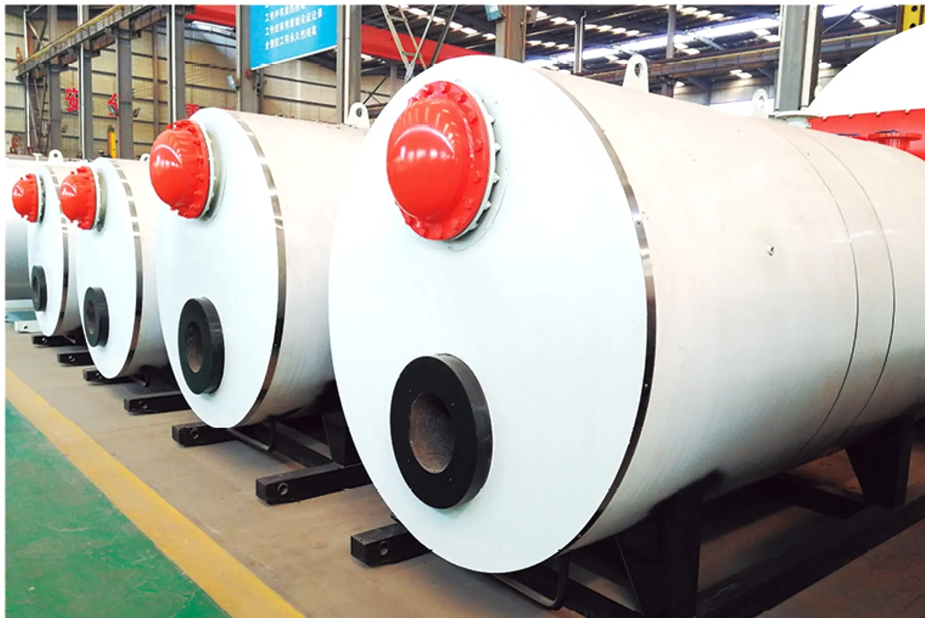
A gas- or oil-fired vacuum phase-change boiler with a built-in heat exchanger, engineered to keep the sealed internal heat medium separate from the customer hot-water circuit.
- Listed Model Range
- 0.24–3.5 MW
- Listed Water Temperatures
- 80 / 60°C
- Listed Thermal Efficiency
- 93%
- Fuel Routes
- Gas / Oil
PRODUCT OVERVIEW
Low-Pressure Internal Phase Change. Isolated User Water.
The ZKS series is a horizontal gas- or oil-fired vacuum hot-water boiler. Combustion heats a sealed internal heat medium under vacuum conditions. The medium evaporates at a reduced temperature, transfers heat to the built-in heat exchanger and condenses back into the vessel.
The customer water circulates through the built-in exchanger rather than mixing with the sealed phase-change medium. This separation helps keep the user-water circuit clean and allows the boiler body, exchanger, burner, pumps, controls and plant interfaces to be engineered as one coordinated system.
Sealed Vacuum Chamber
The internal heat medium operates in a sealed vessel below atmospheric pressure during normal phase-change operation.
Built-In Heat Exchanger
User water passes through the internal exchanger and remains separated from the boiler-side phase-change medium.
Gas or Oil Combustion
The matched burner and fuel train are selected from the approved fuel, heat duty, load profile and emissions target.
Complete Hot-Water Loop
Circulation pumps, make-up water, treatment, controls, heat recovery, chimney and customer interfaces are defined together.
VACUUM PHASE-CHANGE PRINCIPLE
Combustion Heat Crosses Two Deliberately Separated Circuits.
The burner transfers heat into the sealed vacuum vessel. The internal medium evaporates, rises to the built-in exchanger and releases latent heat as it condenses. The condensate then returns by gravity for continuous phase-change circulation.
Customer water flows only through the built-in exchanger and the external heating loop. The circulation pumps deliver heated water to the load and return cooler water to the exchanger without mixing it with the sealed internal medium.
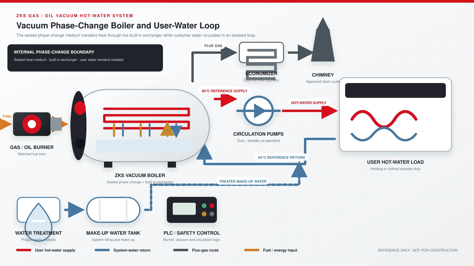
REFERENCE SYSTEM DIAGRAM
How the ZKS Boiler Connects to the User Hot-Water Loop.
The diagram distinguishes the sealed phase-change boundary inside the boiler from the external user-water circuit. Final pipe sizes, pump duties, valves, instruments, redundancy, heat recovery and local-code provisions follow the approved calculations and drawings.
DESIGN FEATURES
Designed Around Phase-Change Heat Transfer and Circuit Separation.
Vacuum Operating Principle
The sealed medium changes phase below atmospheric pressure, supporting hot-water generation without pressurizing the boiler vessel like a conventional pressure boiler.
Built-In Stainless Exchanger
The current technical data specifies a built-in stainless-steel exchanger for efficient heat transfer and clean customer-side water.
Internal Flow Enhancement
The technical data describes internal smoke-tube turbulence elements intended to strengthen heat transfer within a compact structure.
Integrated Compact Arrangement
The boiler vessel and heat exchanger are combined to reduce the required plant footprint and simplify the main equipment boundary.
Matched Burner Package
Burner output, turndown, fuel train, electrical standard and emissions option are selected from the actual project requirement.
Vacuum & Circulation Protection
Vacuum, temperature, water level, circulation and burner permissives are coordinated through the approved safety-control logic.
TECHNICAL DATA
ZKS Reference Models from the Current JINHONG Technical Data.
These are verified listed values for initial discussion. Final capacity, burner, exchanger, pumps, controls, heat recovery and overall arrangement must be confirmed against the actual heat load and approved technical proposal.
| Model | ZKS0.24-80/60-YQ | ZKS0.35-80/60-YQ | ZKS0.49-80/60-YQ | ZKS0.7-80/60-YQ | ZKS1.05-80/60-YQ | ZKS1.4-80/60-YQ | ZKS2.1-80/60-YQ | ZKS2.8-80/60-YQ | ZKS3.5-80/60-YQ |
|---|---|---|---|---|---|---|---|---|---|
| Rated Heating Capacity × 104 kcal/h | 20 | 30 | 40 | 60 | 90 | 120 | 180 | 240 | 300 |
| Outlet Water Temperature °C | 80 | 80 | 80 | 80 | 80 | 80 | 80 | 80 | 80 |
| Return Water Temperature °C | 60 | 60 | 60 | 60 | 60 | 60 | 60 | 60 | 60 |
| Listed Thermal Efficiency % | 93 | 93 | 93 | 93 | 93 | 93 | 93 | 93 | 93 |
| Natural Gas Consumption m³/h | 28.6 | 42.9 | 57.1 | 85.7 | 128.6 | 171.4 | 257.1 | 342.9 | 428.6 |
| LPG Consumption m³/h, stated basis | 22.9 | 34.3 | 45.7 | 68.6 | 102.9 | 137.1 | 205.7 | 274.3 | 342.9 |
| City Gas Consumption m³/h | 60 | 90 | 120 | 180 | 270 | 360 | 540 | 720 | 900 |
| Light Oil Consumption kg/h | 23.5 | 35.3 | 47.1 | 70.6 | 105.9 | 141.2 | 211.8 | 282.4 | 352.9 |
| Heavy Oil Consumption kg/h | 24 | 36 | 48 | 72 | 108 | 144 | 216 | 288 | 360 |
| Air Supply Pressure kPa | 2–4 | 3–4 | 3–5 | 3–6 | 4–6 | 6–10 | 6–10 | 6–10 | 6–10 |
| Power Consumption kW | 0.19 | 0.23 | 0.37 | 0.58 | 0.71 | 1.01 | 1.01 | 1.01 | 1.01 |
| Reference Voltage V | 380 | 380 | 380 | 380 | 380 | 380 | 380 | 380 | 380 |
| Transport Weight t | 1.8 | 2.0 | 2.2 | 3.0 | 3.5 | 4.2 | 5.8 | 7.5 | 10 |
| Reference Overall Size L × W × H, mm | 2500 × 1500 × 1800 | 2800 × 1500 × 1800 | 2900 × 1500 × 1800 | 3800 × 1700 × 2000 | 3800 × 1800 × 2000 | 4200 × 1900 × 2200 | 4200 × 2000 × 2300 | 5400 × 2200 × 2600 | 6800 × 2400 × 2800 |
Fuel basis: The listed values use lower heating values of 8,400 kcal/Nm³ for natural gas, 10,500 kcal/Nm³ for LPG, 4,000 kcal/Nm³ for city gas, 10,200 kcal/kg for light oil and 10,000 kcal/kg for heavy oil.
Fuel consumption: Reference only. Actual use varies with delivered fuel, operating load, burner tuning, water temperatures, ambient conditions, heat recovery and system losses.
Efficiency: The current model table lists 93%. Project performance depends on fuel, load profile, return-water temperature, heat-recovery arrangement, maintenance and the agreed test boundary.
Dimensions and weight: Reference only. Use the approved general-arrangement drawing for transport, lifting, foundation, access and maintenance planning.
FUEL & BURNER ENGINEERING
Select the Burner from the Actual Fuel and Load Profile.
A dependable proposal requires more than the words gas or oil. Provide the real fuel composition or heating value, inlet pressure and temperature, required turndown, local emissions limit, electrical standard and expected daily load pattern.
Send fuel and heating data- 01Natural Gas
Provide composition or lower heating value, inlet pressure, available flow and required pressure regulation.
- 02LPG or City Gas
Different heating values and supply characteristics change burner sizing, fuel-train components and consumption.
- 03Light or Heavy Oil
Viscosity, temperature, storage, filtration, pumping and atomization requirements must be confirmed.
- 04Burner Turndown
The burner should follow the real load profile without excessive cycling at low hot-water demand.
- 05Emissions Target
State the applicable NOx and other local limits before the burner and heat-recovery route are finalized.
- 06Site Standard
Confirm voltage, frequency, altitude, ambient temperature, fuel standard and destination-code requirements.
BOILER & SYSTEM BOUNDARY
A Complete ZKS Plant Extends Beyond the Boiler Body.
The vacuum boiler must be coordinated with the matched burner and fuel train, customer-water pumps, make-up water, water treatment, controls, heat recovery, chimney, electrical supply and every plant connection.
The sealed internal heat medium is part of the boiler phase-change boundary. The customer-water circuit remains separate through the built-in heat exchanger, so its flow, pump head, expansion, pressure rating and terminal equipment must be defined from the actual plant.
Define the system boundaryPlant piping, building pumps, terminal equipment, domestic-water preparation, civil works, installation, local approvals and utilities are included only when explicitly listed in the agreed supply scope.
APPLICATIONS
Clean User-Water Circulation for Heating and Indirect Process Duty.
Application suitability depends on the useful heat load, supply and return temperatures, circuit pressure, water quality, operating schedule and local requirements—not the industry name alone.
Hotels & Commercial Buildings
Central heating and service-hot-water preparation through an approved hygienic heat-exchange arrangement.
Hospitals & Campuses
Heating and hot-water systems where circuit separation, stable operation and equipment-room planning are important.
Industrial Space Heating
Factories, warehouses and workshops supplied through a defined circulation and terminal-water system.
Food & Beverage Plants
Cleaning, washing and indirect process heating through a suitable sanitary or process heat exchanger.
Swimming Pools & Leisure Facilities
Pool-water and domestic-water preparation through correctly selected corrosion-resistant heat exchangers.
Greenhouses & Agriculture
Low-temperature distribution circuits sized from climate, growing area, envelope losses and control zones.
SELECTION GUIDANCE
Select the ZKS Model from the Heat Balance and User-Water Circuit.
A reliable proposal verifies normal and peak heat duty, design temperatures, system flow and pressure, then defines the built-in exchanger, pumps, fuel input, heat loss, redundancy and control boundary.
Review industry solutions- 01Useful Heat Load
Provide normal and peak kW or kcal/h, operating hours and simultaneous demand instead of floor area alone.
- 02Supply & Return Temperatures
The required temperature difference determines circulation flow, exchanger duty and pump selection.
- 03User-Circuit Pressure
State the operating and design pressure of the external water loop so the exchanger and accessories can be matched.
- 04Water Quality & Make-Up
Send raw-water analysis, make-up rate and expected leakage so the treatment route can be defined.
- 05Fuel & Emissions
Provide fuel data, inlet conditions, operating profile and the applicable emissions requirements.
- 06Site Conditions
Confirm altitude, ambient temperature, power supply, boiler-room access, chimney route and destination codes.
FREQUENTLY ASKED QUESTIONS
ZKS Vacuum Hot Water Boiler FAQ.
What capacity range is listed for the JINHONG ZKS series?
The current JINHONG technical data lists models from 0.24 to 3.5 MW, with rated heating-capacity values from 20 to 300 × 104 kcal/h. Final selection follows the project heat balance and system losses.
How is a ZKS vacuum boiler different from a CWNS atmospheric boiler?
The ZKS uses a sealed internal phase-change medium and a built-in exchanger that separates the user-water circuit. The CWNS heats its atmospheric boiler-water circuit directly. System selection depends on the required circuit arrangement, pressure, water quality and project duty.
Does customer water mix with the internal phase-change medium?
No. Customer water circulates through the built-in heat exchanger and external plant loop. The sealed phase-change medium remains inside the boiler vacuum boundary.
What do the 80/60°C values mean?
They are the outlet and return water temperatures listed in the current ZKS model table. Other design temperatures require engineering review because they change flow, exchanger duty, pump selection and system performance.
Can the ZKS boiler use a dual-fuel burner?
A gas/oil dual-fuel burner can be evaluated when both fuels and changeover requirements are defined. It is not assumed by the model name and must be explicitly included in the approved burner, fuel-train and control scope.
Are the listed fuel-consumption values guaranteed?
No. They are reference values based on the stated lower heating values and stated conditions. Actual consumption depends on delivered fuel, load, tuning, temperatures, heat recovery, ambient conditions and the agreed test boundary.
What information is needed for a ZKS technical proposal?
Send normal and peak heat load, supply and return temperatures, external-circuit pressure and flow, application, operating hours, water analysis, fuel data, emissions target, power supply, altitude, destination and required scope.
START WITH HEAT-LOAD & CIRCUIT DATA
Get a ZKS Proposal Matched to Your Load, Fuel and User-Water System.
Send the normal and peak heat demand, temperatures, circuit pressure and flow, application, operating hours, water analysis, fuel data, emissions target and destination. JINHONG will define the boiler and complete system boundary for technical review.