
DOUBLE-DRUM BIOMASS WATER-TUBE BOILER
SZL Biomass Water Tube Steam Boiler
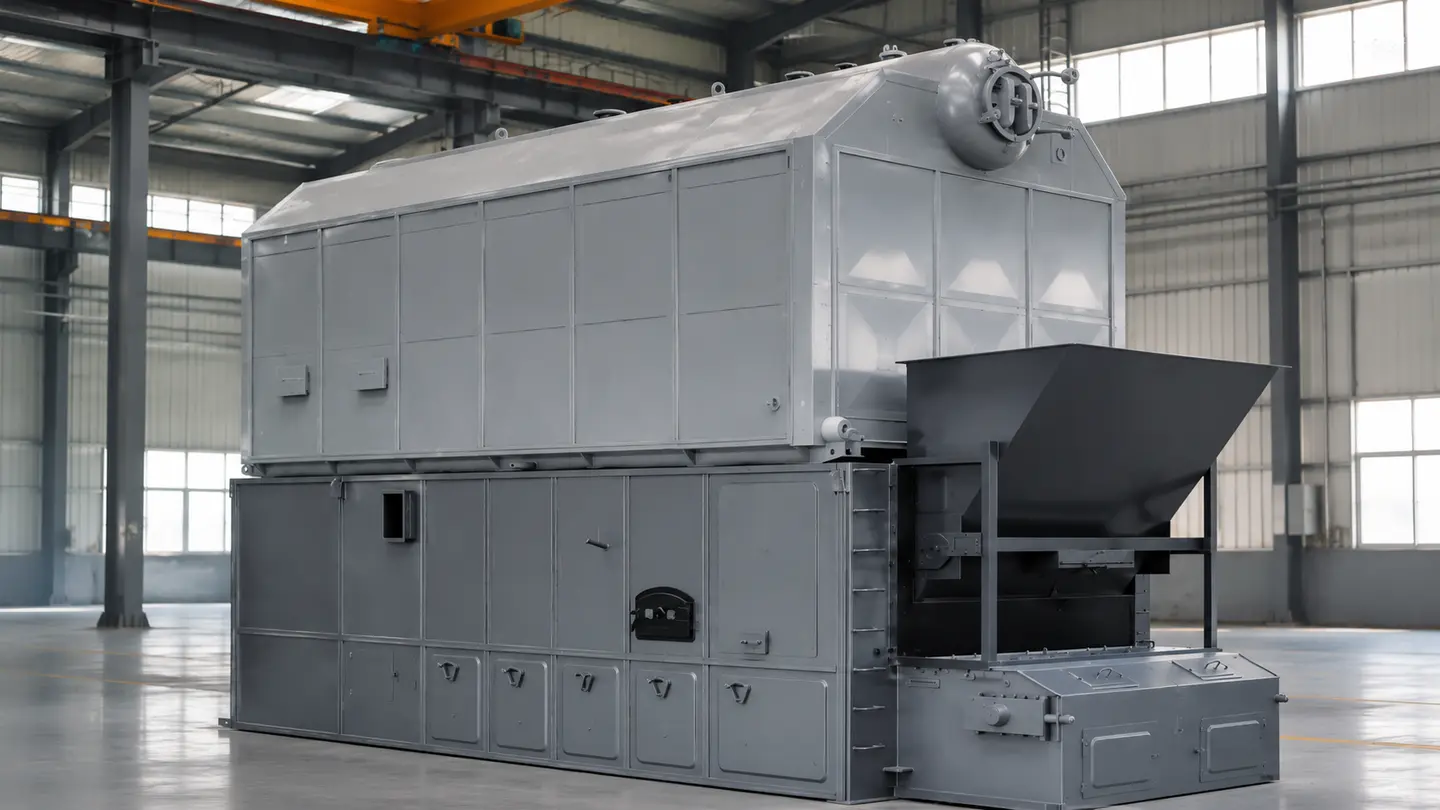
A higher-capacity solid-fuel steam-boiler route combining longitudinal double drums, water-tube heating surfaces and a travelling chain grate, configured around fuel properties, steam pressure and continuous industrial load.
- Steam Capacity
- 4–35 t/h
- Pressure Routes
- 1.25–2.5 MPa
- Boiler Structure
- Double Drum
- Firing System
- Chain Grate
PRODUCT OVERVIEW
Water-Tube Capacity for Steady Medium- and Large-Steam Loads.
The SZL series combines a horizontal longitudinal double-drum water-tube boiler body with a travelling chain grate. The steam-water circuit, furnace heating surfaces and convection tube banks are arranged for continuous industrial duty.
The JINHONG SZL product range covers 4–35 t/h steam routes. Final selection must coordinate steam demand, working pressure, fuel analysis, circulation design, grate and furnace sizing, transport sections and local emission requirements.
Double-Drum Circulation
The upper and lower drums, headers and water-cooled surfaces form the configured steam-water circulation route.
Water-Tube Heating Surfaces
Furnace-side surfaces and convection tube banks provide the heat-transfer area required for the selected load.
Continuous Chain-Grate Firing
Mechanized fuel travel and zoned air distribution support stable combustion across continuous operation.
Sectional Delivery Planning
Model size, inland transport, lifting capacity and site access determine the approved shipping and assembly route.
STEAM-WATER & COMBUSTION ROUTE
The Water-Tube Circuit and Chain-Grate Furnace Must Be Engineered as One System.
Prepared biomass is distributed onto the travelling grate and passes through drying, ignition, main combustion and burnout zones. Furnace heat is absorbed by the configured water-cooled surfaces before the flue gas crosses the convection tube banks.
Feedwater enters the approved heat-recovery and drum circuit. The upper and lower drums, headers and water tubes support steam-water circulation, while separated steam leaves through the configured outlet and safety system.
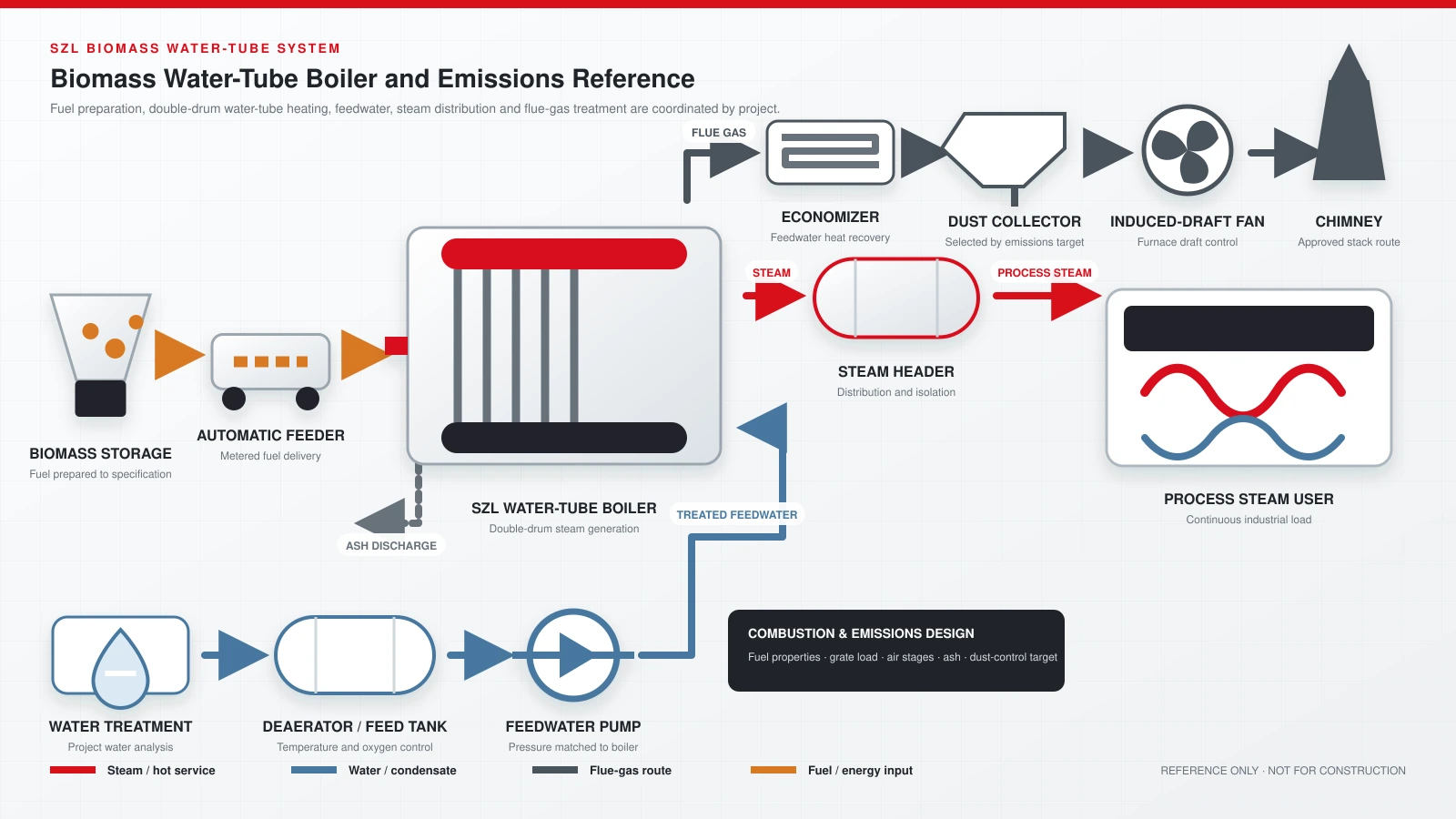
REFERENCE SYSTEM DIAGRAM
How Fuel, Steam, Water and Emissions Equipment Connect Around SZL.
The diagram shows a coordinated double-drum biomass route from fuel storage and automatic feeding through steam generation, feedwater, heat recovery, dust removal, induced draft and chimney discharge.
For feedwater heat-recovery planning, review the boiler economizer selection guide. Economizer inclusion, materials and sizing remain project-specific.
DESIGN FEATURES
Double-Drum Water-Tube Construction for Higher Continuous Loads.
The following features describe the current JINHONG SZL product route. Final materials, construction details, component brands and performance requirements follow the approved technical proposal and drawings.
01 / CIRCULATION
Longitudinal Double Drums
The configured drum and header circuit supports water circulation and steam separation across the selected pressure route.02 / FURNACE
Water-Cooled Heating Surfaces
Furnace-side water tubes absorb radiant heat and protect the pressure-part circuit under continuous firing.03 / HEAT TRANSFER
Convection Tube Banks
Dense water-tube surfaces recover heat from the gas path before downstream economizer and emission equipment.04 / FIRING
Travelling Chain Grate
Mechanized fuel travel and zoned combustion air are configured for the approved biomass fuel.05 / ACCESS
Inspection and Cleaning Access
Access points support furnace, grate, ash, drum and tube-surface inspection during planned maintenance.06 / DELIVERY
Fast or Sectional Assembly
the product range includes a fast-assembly route at 4 t/h and major upper/lower transport sections for larger capacities.TECHNICAL DATA
Reference Configurations for Initial SZL Selection.
The JINHONG SZL product range lists seven steam-capacity routes. Final model, pressure, fuel basis, efficiency, transport sections, emission equipment and auxiliary configuration follow the approved technical proposal and drawings.
| Rated Capacity | 4 t/h | 6 t/h | 8 t/h | 10 t/h | 15 t/h | 20 t/h | 35 t/h |
|---|---|---|---|---|---|---|---|
| Rated Pressure MPa | 1.25 / 1.6 / 2.5 | 1.25 / 1.6 / 2.5 | 1.25 / 1.6 / 2.5 | 1.25 / 1.6 / 2.5 | 1.25 / 1.6 / 2.5 | 1.25 / 1.6 / 2.5 | 1.25 / 1.6 / 2.5 |
| Saturated Steam Temperature °C | 194 / 204 / 226 | 194 / 204 / 226 | 194 / 204 / 226 | 194 / 204 / 226 | 194 / 204 / 226 | 194 / 204 / 226 | 194 / 204 / 226 |
| Reference Feedwater Temperature °C | 20 | 20 | 20 | 20 | 20 | 20 | 20 |
| Effective Grate Area m² | 6.72 | 7.52 | 10.25 | 11.8 | 18 | 23.2 | 33.7 |
| Fuel Consumption kg/h | ≈768 | ≈1,185 | ≈1,570 | ≈1,900 | ≈2,900 | ≈3,850 | ≈6,800 |
| Reference Exhaust-Gas Temperature °C | 105–120 | 105–120 | 105–120 | 95–110 | 95–110 | 95–110 | 95–110 |
| Thermal-Efficiency Range | 85–86% | 85–86% | 85–86% | 86–91% | 86–91% | 86–91% | 86–91% |
| Rated Capacity | 4 t/h | 6 t/h | 8 t/h | 10 t/h | 15 t/h | 20 t/h | 35 t/h |
|---|---|---|---|---|---|---|---|
| Assembly Route | Fast assembly | Upper / lower sections | Upper / lower sections | Upper / lower sections | Upper / lower sections | Upper / lower sections | Multiple major sections |
| Approx. Largest-Part Weight | 30 t | 22.5 t | 25 t | 28 t | 30 t | 35 t | 52 t |
| Largest Transport Section L × W × H | 7.73 × 2.36 × 3.62 m | Upper 6.15 × 2.84 × 3.54 m Lower 7.28 × 2.85 × 2.58 m | Upper 6.97 × 2.90 × 3.54 m Lower 8.07 × 2.95 × 2.58 m | Upper 7.87 × 3.24 × 3.54 m Lower 9.03 × 3.20 × 2.58 m | Upper 10.00 × 3.24 × 3.54 m Lower 12.00 × 3.20 × 3.06 m | Upper 11.00 × 3.24 × 3.54 m Lower 14.00 × 3.20 × 3.08 m | Upper 8.50 × 1.83 × 1.85 m Lower 14.08 × 4.40 × 3.17 m |
Fuel-consumption basis: the listed consumption is technical data, not a guaranteed project value. The approved calculation must use the actual lower heating value, moisture, ash, unburned-carbon loss, operating load and system condition.
Selection note: all values above are preliminary reference data from the SZL product data. Final output, pressure, efficiency, transport sections, emissions and component configuration follow the signed technical agreement and approved drawings.
FUEL ENGINEERING
Higher Capacity Makes Fuel Consistency More Important, Not Less.
the product range includes biomass pellets, rice husk, plant straw and agricultural residues as fuel routes, but these fuels do not share the same storage, conveying, grate, furnace, air or dust-removal design.
A representative sample and laboratory report are required before JINHONG fixes the combustion system. Stable output depends on matching fuel preparation and furnace design to the continuous load.
Lower Heating Value
Provide the as-fired net calorific value, not only a generic fuel name.
Moisture and Ash
These values affect ignition, furnace temperature, flue-gas volume and ash handling.
Particle Size and Density
Fuel dimensions and bulk density determine storage, conveying and fuel-bed behavior.
Ash Fusion and Contaminants
Slagging tendency, alkali content, soil, stones, metal and mixed waste must be identified before design.
PRESSURE PARTS & COMPLETE SYSTEM
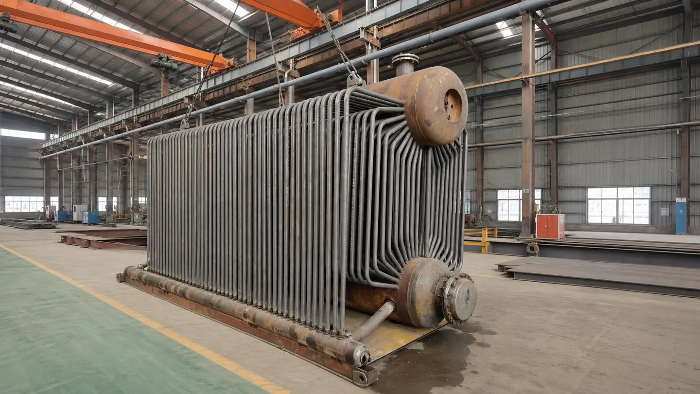
Tube Banks, Drums, Furnace and Auxiliaries Must Be Coordinated Before Manufacturing.
A reliable SZL project integrates the pressure-part circuit with the grate, furnace, fuel handling, forced and induced draft, feedwater, heat recovery, dust removal, controls, ash handling and the customer’s steam network.
Not every item is included by default. The final supply boundary, emission equipment, electrical scope, component brands and site interfaces are stated in the approved proposal.
Define your system boundaryINDUSTRIAL APPLICATIONS
For Plants with Higher, Steady Steam Demand and a Controlled Biomass Supply.
Industry name alone cannot select the boiler. Steam load, working pressure, operating hours, fuel consistency, water quality, emission limits and space must be reviewed together.
Textile & Dyeing
Steam for washing, dyeing, drying and finishing where a prepared biomass fuel supply is available.
Explore solution →Food Processing
Process steam for cooking, cleaning, sterilization and thermal production duties.
Explore solution →Paper & Packaging
Steam for drying, corrugating, process heating and continuous utility loads.
Explore solution →Palm Oil & Rice Mills
Steam for sterilization, parboiling, drying and processing, with fuel preparation matched to local residues.
Explore solution →Feed Mills
Steam for conditioning, pelleting and process-heating duties across production lines.
Explore solution →Wood Processing
Steam for veneer, plywood, drying and pressing where suitable wood residues are controlled.
Explore solution →SELECTION INPUTS
Send the Steam Profile, Fuel Report and Site Transport Limits.
JINHONG engineers use these inputs to determine whether SZL is the correct route and to define the capacity, pressure, circulation circuit, grate, furnace, air system, transport sections and dust-removal equipment.
Send Project Data- 01Steam RequirementNormal and peak load, pressure, hours per day and load variation
- 02Fuel ReportHeating value, moisture, ash, size, bulk density and annual availability
- 03Water & CondensateRaw-water analysis, feedwater route and condensate-return condition
- 04Site, Lifting & EmissionsDestination, elevation, available footprint, road limits, crane capacity and local standards
- 05Supply BoundaryFuel handling, dust collection, installation guidance, electrical standard and documentation
FREQUENTLY ASKED QUESTIONS
SZL Biomass Water-Tube Boiler Selection Questions.
What is the main difference between SZL and DZL?
SZL uses a longitudinal double-drum water-tube arrangement and is positioned for higher continuous steam loads and pressure routes. DZL is a single-drum route typically used at lower capacities. The correct choice still depends on load, fuel, pressure, transport and site conditions.
Which SZL capacities are listed in the SZL product range?
The JINHONG SZL product range lists 4, 6, 8, 10, 15, 20 and 35 t/h steam-capacity routes with 1.25, 1.6 and 2.5 MPa pressure options.
Can SZL burn rice husk or plant straw?
These fuels are listed as possible routes, but they require project-specific review. Bulk density, moisture, ash chemistry, particle form and carryover determine the feeding, grate, furnace, air and dust-removal design.
Is an SZL boiler delivered as one complete unit?
the product range includes a fast-assembly route at 4 t/h. Larger models normally require major transport sections and site assembly planning based on road, port, lifting and boiler-room access limits.
Is fuel feeding fully automatic?
The chain grate provides mechanized fuel movement. Storage, conveying, metering, feeding and ash-handling automation depend on the approved fuel route and supply boundary.
Is the dust collector included?
Not automatically in every proposal. Dust collection and any additional flue-gas treatment are selected from the fuel ash, emission requirements and destination standard, then listed clearly in the approved scope.
START WITH LOAD, FUEL & SITE
Get an SZL Proposal Based on Your Steam Profile and Biomass Data.
Send the normal and peak load, working pressure, operating hours, destination, transport limits and fuel report. JINHONG will define the suitable boiler and system boundary for technical review.